 |
am2zzw00005698
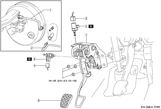
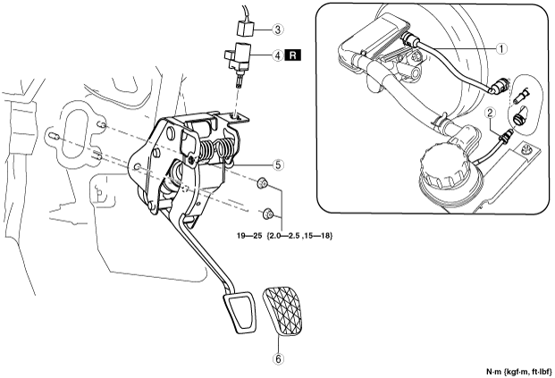
CLUTCH PEDAL REMOVAL/INSTALLATION [F35M-R]
id051005801200
1. Disconnect the negative battery cable. (See BATTERY REMOVAL/INSTALLATION [MZR 1.3, MZR 1.5].)
2. Remove the battery clamp and battery box and battery. (L.H.D.) (See BATTERY REMOVAL/INSTALLATION [MZR 1.3, MZR 1.5].)
3. Remove in the order indicated in the table.
4. Plug the clutch pipe after removing it to avoid leakage.
5. Install in the reverse order of removal.
6. Fully depress the clutch pedal, and verify that the engine starts.
L.H.D.
am2zzw00005698
|
|
1
|
Reserve hose
(See Reserve Hose Removal Note.)
|
|
2
|
Clutch pipe
(See Clutch Pipe Removal Note.)
|
|
3
|
Clutch pedal position switch connector
|
|
4
|
Clutch pedal position switch
|
|
5
|
Clutch pedal component
|
|
6
|
Pedal pad
|
R.H.D.
am2zzw00005630
|
|
1
|
Reserve hose
(See Reserve Hose Removal Note.)
|
|
2
|
Clutch pipe
(See Clutch Pipe Removal Note.)
|
|
3
|
Clutch pedal position switch connector
|
|
4
|
Starter interlock switch connector (General (R.H.D.) specs)
|
|
5
|
Clutch pedal position switch
|
|
6
|
Starter interlock switch (General (R.H.D.) specs)
|
|
7
|
Clutch pedal component
|
|
8
|
Pedal pad
|
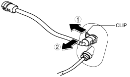
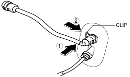
Reserve Hose Removal Note
1. Move the clip upward.
am2zzw00005631
|
2. Disconnect the reserve hose.
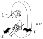
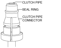
Clutch Pipe Removal Note
1. Pull the clutch master cylinder clip to the position shown in the figure and pull out the clutch pipe connector straight to detach it.
am2zzw00000173
|
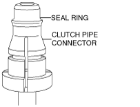
2. Verify that the seal ring is removed together with the clutch pipe connector.
am2zzw00003987
|
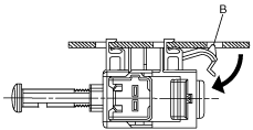
Starter Interlock Switch Removal Note
1. Detach hook B in the direction of the arrow shown in the figure.
am2zzw00005862
|
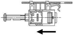
2. Remove the starter interlock switch by sliding the switch in the direction of the arrow
am2zzw00005699
|
Clutch Pedal Component Installation Note
1. Add the clutch fluid, bleed the air, and inspect for leakage after the installation. (See CLUTCH FLUID AIR BLEEDING/REPLACEMENT [F35M-R].)
2. After installing the clutch pedal, inspect the clutch pedal. (See CLUTCH PEDAL INSPECTION [F35M-R].)
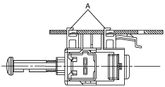
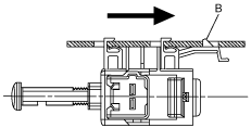
Starter Interlock Switch Installation Note
1. Insert the new starter interlock switch.
am2zzw00005700
|
am2zzw00005701
|
2. Fully depress the clutch pedal, and verify that a click sound from the starter interlock switch is heard.
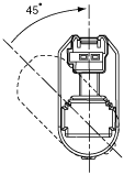
Clutch Pedal Position Switch Installation Note
1. Insert the new clutch pedal position switch into hole of the pedal bracket until the switch stops.
2. Rotate the clutch pedal position switch 45° clockwise.
am3zzw00002990
|
3. Verify that the clutch pedal position switch is locked securely.
Clutch Pipe Installation Note
1. Verify that the seal ring is assembled to the clutch pipe so that the ends of the seal ring and the clutch pipe overlap each other.
am2zzw00003960
|
2. Return the clutch master cylinder clip to the position shown in the figure.
am2zzw00000174
|
3. Insert the clutch pipe connector straight.
4. Pull the clutch pipe to verify that it does not come off, and reinsert it completely.
Reserve Hose Installation Note
1. Connect the reserve hose until a click is heard.
am2zzw00005632
|
2. Verify that the reserve hose is securely installed by pulling it, and reinsert into the reserve tank.