 |
am2zzw00002205
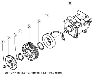
MAGNETIC CLUTCH DISASSEMBLY/ASSEMBLY [FULL-AUTO AIR CONDITIONER]
id0740a1800400
1. Assemble in the reverse order of disassembly.
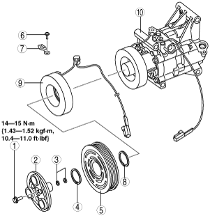
MZR 1.3, MZR 1.5 (Type A)*1
am2zzw00002205
|
|
1
|
Bolt
|
|
2
|
Pressure plate
|
|
3
|
Shim
|
|
4
|
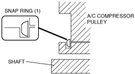
Snap ring (1)
|
|
5
|
A/C compressor pulley
|
|
6
|
Screw
|
|
7
|
Clamp
(See Clamp Installation Note.)
|
|
8
|
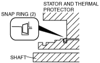
Snap ring (2)
|
|
9
|
Stator and thermal protector
|
|
10
|
A/C compressor body
|
MZR 1.3, MZR 1.5 (Type B)*2
am2llw00000051
|
|
1
|
Bolt
|
|
2
|
Washer
|
|
3
|
Pressure plate
|
|
4
|
Shim
|
|
5
|
Snap ring (1)
|
|
6
|
A/C compressor pulley
|
|
7
|
Snap ring (2)
|
|
8
|
Stator
|
|
9
|
A/C compressor body
|
MZ-CD 1.6
am2zzw00002970
|
|
1
|
Nut
|
|
2
|
Pressure plate
|
|
3
|
Shim
|
|
4
|
Snap ring (1)
|
|
5
|
A/C compressor pulley
|
|
6
|
Snap ring (2)
|
|
7
|
Stator
|
|
8
|
A/C compressor body
|
2. Assemble in the reverse order of disassembly.
3. Adjust the magnetic clutch clearance. (See MAGNETIC CLUTCH ADJUSTMENT [FULL-AUTO AIR CONDITIONER].)
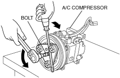
Bolt Removal/Installation Note (MZR 1.3, MZR 1.5 (Type A)*1)
1. When removing or installing the bolt, hold the pressure plate in place as shown in the figure.
am2zzw00005573
|
2. When installing a new A/C compressor body, replace the bolt.
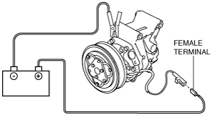
Bolt Removal/Installation Note (MZR 1.3, MZR 1.5 (Type B)*2)
1. When removing or installing the bolt, lock A/C compressor pulley against rotation using the following procedure.
am2llw00000052
|
am2llw00000053
|
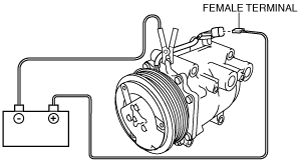
Nut Removal/Installation Note
1. When removing or installing the nut, lock A/C compressor pulley against rotation using the following procedure.
am2zzw00002971
|
am2zzw00002972
|
Stator and Thermal Protector Removal Note
1. After removing the stator and thermal protector, completely remove the silicone adhering to the A/C compressor side.
Stator and Thermal Protector Installation Note
1. Apply approx. 1 g {0.04 oz} of silicone (Shin-Etsu Silicone KE-347W or similar) to the contact surface of the thermal protector, then thoroughly install it onto the A/C compressor, leaving no gaps.
am2zzw00005574
|
Snap Ring (2) Installation Note
1. When installing a stator and thermal protector, replace the snap ring (2).
am2zzw00005575
|
Clamp Installation Note
1. When installing a new stator and thermal protector, replace the clamp.
Snap Ring (1) Installation Note
1. When installing a new pressure plate, A/C compressor pulley, stator, or A/C compressor body, replace the snap ring (1).
am2zzw00005576
|
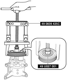
A/C Compressor Pulley Removal Note (MZR 1.3, MZR 1.5 (Type B)*2)
1. Remove the A/C compressor pulley using the SST (49 0839 425C, 49 U027 001).
am2llw00000054
|
e5u740zw5021
|
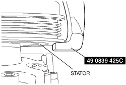
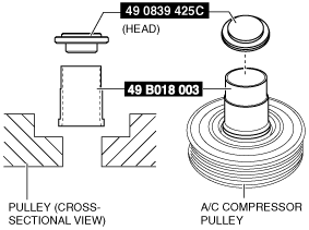
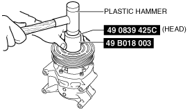
A/C Compressor Pulley Installation Note (MZR 1.3, MZR 1.5 (Type B)*2)
1. Set the SSTs (49 0829 425C (HEAD), 49 B018 003) as shown in the figure.
am2llw00000055
|
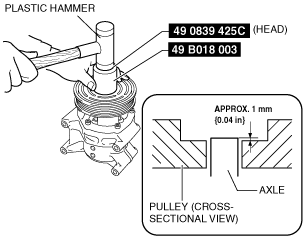
2. Insert the compressor pulley to the position shown in the figure using the SSTs (49 0829 425C (HEAD), 49 B018 003) and a plastic hammer.
am2llw00000056
|
am2llw00000057
|
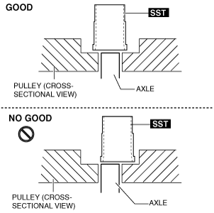
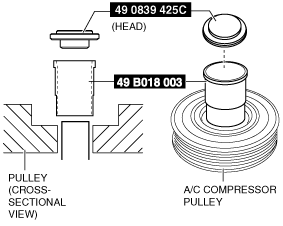
3. Set the SSTs (49 0829 425C (HEAD), 49 B018 003) as shown in the figure.
am2llw00000058
|
4. Insert the compressor pulley using the SSTs (49 0829 425C (HEAD), 49 B018 003) and a plastic hammer.
am2llw00000059
|