 |
am2zzw00006114
DTC U201F:00 [ADVANCED KEYLESS AND START SYSTEM]
id0902e1388800
Description
Possible Causes
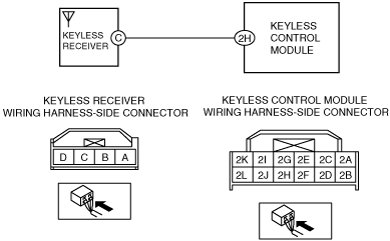
System Wiring Diagram
am2zzw00006114
|
Diagnostic Procedure
|
Step |
Inspection |
Action |
|
|---|---|---|---|
|
1
|
INSPECT KEYLESS RECEIVER CONNECTOR AND TERMINALS
• Turn the ignition switch to the LOCK position.
• Disconnect the negative battery cable.
• Disconnect the keyless receiver connector.
• Inspect the connector and terminals (corrosion, damage, pin disconnection).
• Is there any malfunction?
|
Yes
|
Repair or replace the connector or terminals, then go to Step 7.
|
|
No
|
Go to the next step.
|
||
|
2
|
INSPECT KEYLESS CONTROL MODULE CONNECTOR AND TERMINALS
• Disconnect the keyless control module connector.
• Inspect the connector and terminals (corrosion, damage, pin disconnection).
• Is there any malfunction?
|
Yes
|
Repair or replace the connector or terminals, then go to Step 7.
|
|
No
|
Go to the next step.
|
||
|
3
|
INSPECT KEYLESS RECEIVER CIRCUIT FOR SHORT TO GROUND
• Verify that the keyless receiver and keyless control module connectors are disconnected.
• Inspect for continuity between keyless receiver terminal C (wiring harness-side) and body ground.
• Is there continuity?
|
Yes
|
Repair or replace the wiring harness for a possible short to ground, then go to Step 7.
|
|
No
|
Go to the next step.
|
||
|
4
|
INSPECT KEYLESS RECEIVER CIRCUIT FOR SHORT TO POWER SUPPLY
• Verify that the keyless receiver and keyless control module connectors are disconnected.
• Reconnect the negative battery cable.
• Turn the ignition switch to the ON position.
• Measure the voltage at the keyless receiver terminal C (wiring harness-side).
• Is there any voltage?
|
Yes
|
Repair or replace the wiring harness for a possible short to power supply, then go to Step 7.
|
|
No
|
Go to the next step.
|
||
|
5
|
INSPECT KEYLESS RECEIVER CIRCUIT FOR OPEN CIRCUIT
• Verify that the keyless receiver and keyless control module connectors are disconnected.
• Turn the ignition switch to the LOCK position.
• Disconnect the negative battery cable.
• Inspect for continuity between the keyless receiver terminal C (wiring harness-side) and keyless control module terminal 2H (wiring harness-side).
• Is there continuity?
|
Yes
|
Go to the next step.
|
|
No
|
Repair or replace the wiring harness for a possible open circuit, then go to Step 7.
|
||
|
6
|
INSPECT KEYLESS RECEIVER
• Inspect the keyless receiver.
• Is there any malfunction?
|
Yes
|
Replace the keyless receiver, then go to the next step.
|
|
No
|
Go to the next step.
|
||
|
7
|
VERIFY TROUBLESHOOTING COMPLETED
• Make sure to reconnect all disconnected connectors.
• Reconnect the negative battery cable.
• Clear the DTCs using the M-MDS.
• Perform the keyless control module DTC inspection using the M-MDS.
• Is the same DTC present?
|
Yes
|
Repeat the inspection from Step 1.
• If the malfunction recurs, replace the keyless control module.
Go to the next step.
|
|
No
|
Go to the next step.
|
||
|
8
|
VERIFY THAT NO OTHER DTCs ARE PRESENT
• Are any DTCs present?
|
Yes
|
Go to the applicable DTC inspection.
|
|
No
|
DTC troubleshooting completed.
|
||