Step
Inspection
Action
1
• Does the operation indicator light (LED) illuminate when the transmitter (advanced key) is operated?
Yes
Go to the next step.
No
Go to Step 10.
2
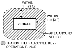
• Did the customer activate the transmitter (advanced key) within operative area (Within 1 m {3 ft} from area around vehicle)?
Yes
Go to the next step.
No
System is normal. (Explain to the customer to operate the transmitter (advanced key) within the operation range.)
3
• Did the customer operate at a place where extrinsic noise is received such as a TV tower, electric power station, or a broadcast station.
Yes
System is normal. (Explain to the customer to operate the transmitter (advanced key) away from extrinsic noise.)
No
Go to the next step.
4
• Did the customer operate the transmitter (advanced key) with all the following conditions met?
-
― All doors and liftgate are closed.― The auxiliary key is not inserted in the ignition key cylinder.― The start knob is in the LOCK position.― The start knob is being pressed.
Yes
Go to the next step.
No
System is normal. (Explain to the customer that the system does not operate due to the cancel function with the auxiliary key in the ignition key cylinder.)
5
• Did the malfunction occur after any non-standard equipment (any control unit with built-in micro computer such as radio set, mobile telephone, and TV) was installed?
Yes
Go to the next step.
No
Go to Step 7.
6
• Turn the ignition switch to the LOCK position.
• Disconnect the negative battery cable.
• Was the malfunction corrected when the connector of the equipment was disconnected?
Yes
System is normal. (Explain to the customer that noise from the equipment affected the operation.)
No
Go to the next step.
7
• Is there repair record of the customer's keyless entry system?
Yes
Go to the next step.
No
Go to Step 10.
8
• Does the malfunction occur after the repair?
Yes
Go to the next step.
No
Go to Step 10.
9
• Is the malfunction corrected when the ID numbers for all the customer's transmitters (advanced key) are updated?
Yes
System is normal. (Explain to the customer that the malfunction occurred because all the transmitter (advanced key) ID numbers were not updated even though the body control module or a transmitter (advanced key) was replaced in the previous servicing.)
No
Go to the next step.
10
• Visually inspect the transmitter (advanced key) battery for the following:
-
― Battery direction (polarity)― Battery type (CR1620)― Corrosion, soiling, deformation of battery terminals (plus/minus terminals).― Contact malfunction between the battery terminal and battery when battery is inserted
• Is there any malfunction?
Yes
Battery insertion direction, battery type problem:
• Properly install the battery or replace the battery with a specified one (CR1620), then go to the next step.
Malfunction with the battery terminals:
• Clean corrosion and soiling or repair the terminal, then go to the next step.
No
Go to Step 12.
11
• Does the keyless entry system operate properly?
Yes
Troubleshooting completed.
No
Go to the next step.
12
-
Note
-
• Use a new monitor battery (normal battery) or one from another vehicle which operates normally.
• Replace the battery in all the transmitters (advanced key) with a monitor-use battery (normal battery).
• Does operation indicator light (LED) for each transmitter (advanced key) operate?
Yes
Go to the next step.
No
If the operation indicator light (LED) does not illuminate, replace the transmitter (advanced key), then go to the Step 24.
13
-
Note
-
• Inspect for all transmitters (advanced key).• Inspect while the batteries for all of the transmitters (advanced key) are replaced with monitor-use batteries (normal battery).
• Verify the operation of keyless entry system using all of the transmitters (advanced key).
• Does the keyless entry system operate properly?
Yes
Replace the transmitter (advanced key) battery, and then go to Step 24.
No
Go to the next step.
14
• Inspect the keyless receiver installation condition.
• Is the bracket installed securely?
Yes
Go to the next step.
No
Install the bracket securely, then go to the next step.
15
• Inspect the keyless receiver.
• Is the keyless receiver power supply voltage normal?
-
― Power supply (+B) (terminal D)
Yes
Go to the next step.
No
Inspect for a burnt fuse (ROOM 15 A)
Inspect the power supply system wiring harness for an open or short circuit.
16
• Inspect the keyless receiver.
• Is the keyless receiver grounded normally?
-
― Power supply (0 V) (terminal B)
Yes
Go to the next step.
No
Inspect the ground system wiring harness for an open circuit.
Inspect the ground tightening screw and nut for looseness.
17
• Turn the ignition switch to the LOCK position.
• Disconnect the negative battery cable.
• Disconnect the keyless receiver connector (4-pin) and the keyless control module connector (12-pin).
• Inspect the wiring harness between the following terminals for an open or short circuit.
-
― Terminal C (4-pin) to terminal 2H (12-pin)
• Is the wiring harness normal?
Yes
Go to the next step.
No
Repair or replace the wiring harness between the keyless receiver connector and keyless control module connector, then go to the next step.
18
• Measure the signal wave pattern of keyless control module terminal 2H using an oscilloscope while the transmitter (advanced key) is operated with the auxiliary key removed from the ignition key cylinder.
• Does the wave pattern change when the transmitter (advanced key) is operated?
-
Note
-
• Perform the oscilloscope setting using 0.5 V/DIV (Y), 100 ms/DIV (X), DC range.
Yes
Go to the next step.
No
Replace the keyless receiver, and then go to Step 24.
19
• Are the following keyless control module power supply voltages normal?
-
― Power supply (IG1) (Terminal 2C)― Power supply (+B) (Terminals 1D and 1E)― Power supply (ACC) (Terminal 2A)
Yes
Go to the next step.
No
Inspect for a burnt fuse (ENG10 A, ROOM15 A, P/W 20 A, MIRROR 7.5 A).
Inspect the power supply system wiring harness for an open or short circuit, repair or replace if necessary, then go to the next step.
20
• Is the following keyless control module ground voltage normal?
-
― 0 V (Terminal 3N)
Yes
Go to the next step.
No
Inspect the ground system wiring harness for an open circuit, then go to the next step.
21
• Inspect the following keyless control module (12-pin, 30-pin) signal voltages with the auxiliary key not in the ignition key cylinder, and the start knob in the LOCK position and not being pressed.
-
― Keyless switch: 10 V or less (Terminal 3W)― Start knob (push switch): 1.0 V or less (Terminal 3V)― Power supply (ACC): 1.0 V or less (Terminal 2A)― Power supply (IG1): 1.0 V or less (Terminal 2C)
• Are the signal voltages normal?
Yes
Go to the next step.
No
Inspect the keyless switch.
Inspect the keyless switch system wiring harness for an open or short circuit, then go to the next step.
22
• Monitor the following PIDs for the BCM using the M-MDS:
-
― DRSW_D (Door latch switch (driver side))― DRSW_P (Door latch switch (passenger side))― DRSW_RR (Door latch switch (rear door (RH)))― DRSW_LR (Door latch switch (rear door (LH)))― TR/LG_SW (Liftgate latch and lock actuator)
• Does each monitor value agree with the door open/close condition?
Yes
• Inspect the wiring harness between BCM terminal 6W and keyless control module terminal 2F.
-
― If there is any open or short circuit, repair or replace the malfunctioning part.― If there is no malfunction, go to the next step.
No
• Inspect the door latch switch.
• Inspect the door latch switch system wiring harness for an open or short circuit, then go to the next step.
23
• Is the signal voltage transmitted from the BCM to the door lock actuator normal?
• Does BCM terminal voltage change as follows when locking/unlocking using the transmitter (advanced key)?
-
― Unlocking: 1.0 V or less→B+→1.0V or less (Terminal 3O)― Locking (Vehicles with double locking system): 1.0 V or less→B+→1.0 V or less (Terminal 3E)― Locking (Vehicles without double locking system): 1.0 V or less→B+→1.0 V or less (Terminal 3M)
Yes
Inspect the following and repair or replace the malfunctioning location.
• Wiring harness between BCM and door lock actuator (open circuit)
• Door lock actuator (Short circuit in internal circuit)
After inspection and repair, go to the next step.
No
Inspect the following and repair or replace themalfunctioning location.
• Wiring harness between BCM and door lock actuator (short circuit)
• If there is no malfunction with the door lock actuator harness (no short circuit in internal circuit) and the door lock actuator, replace the BCM.
• Then go to the next step.
24
• Does the advanced keyless and start system operate normally?
Yes
Troubleshooting completed.
No
Verify the malfunction, then go to Step 1 if it recurs.