INSTRUMENT CLUSTER INSPECTION
id092200496400
MZR 1.3, MZR 1.5
Speedometer Inspection
1. Adjust the tire pressure to the specification.
2. Using a speedometer tester, verify that the tester reading is as indicated in the table.
-
• If the speedometer does not operate or the indication is not within the allowable range, inspect the PCM, ABS HU/CM or DSC HU/CM, and related wiring harnesses.
-
― If the PCM, ABS HU/CM or DSC HU/CM, and related wiring harnesses do not have any malfunction, replace the instrument cluster.
General (L.H.D.) specs.
|
Speedometer tester indication (km/h)
|
Allowable range (km/h)
|
|
20
|
18—22
|
|
40
|
38—42
|
|
60
|
58—62
|
|
80
|
77—83
|
|
100
|
97—103
|
|
120
|
117—123
|
|
140
|
136—144
|
European (L.H.D. U.K.), specs.
|
Speedometer tester indication (km/h)
|
Allowable range (km/h)
|
|
20
|
20—25
|
|
40
|
41—45
|
|
60
|
61—66
|
|
80
|
82—87
|
|
100
|
102—108
|
|
120
|
123—129
|
|
140
|
143—150
|
U.K. specs.
|
Speedometer tester indication (mph)
|
Allowable range (mph)
|
|
10
|
10—13
|
|
20
|
20—23
|
|
30
|
30—34
|
|
40
|
41—44
|
|
50
|
51—55
|
|
60
|
61—66
|
|
70
|
72—76
|
|
80
|
82—87
|
Tachometer
-
Caution
-
• If the engine speed exceeds the allowable range, the engine could be damaged. Therefore, when inspecting the tachometer, do not allow the engine speed to exceed the allowable range indication on the tachometer.
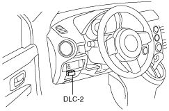
1. Connect the M-MDS (IDS) to the DLC-2.
2. After the vehicle is identified, select the following items from the initialization screen of the IDS.
-
1. “Data logger”
2. “Module”
3. “IC”
3. Select “TACHOMTR” from PID/DATA Monitor Table.
4. Verify the monitored value according to the directions on the screen.
-
Note
-
• The PID data screen function is used for monitoring the calculated value of input/output signals in the module. Therefore, if the monitored value of the output parts is not within the specification, it is necessary to inspect the monitored value of input parts corresponding to the applicable output part control. In addition, because the system does not display an output part malfunction as an abnormality in the monitored value, it is necessary to inspect the output parts individually.
• When detecting DTCs, PIDs related to a malfunctioning system may not display even if the module is normal. Therefore, if a PID is not displayed, it is necessary to verify the DTC, perform malfunction diagnosis of the DTC that was detected, and do repairs.
Fuel gauge
1. Connect the M-MDS (IDS) to the DLC-2.
2. After the vehicle is identified, select the following items from the initialization screen of the IDS.
-
1. “Data logger”
2. “Module”
3. “IC”
3. Verify that all the segments are displayed using “LCD_SEG”.
-
-
Note
-
• The PID data screen function is used for monitoring the calculated value of input/output signals in the module. Therefore, if the monitored value of the output parts is not within the specification, it is necessary to inspect the monitored value of input parts corresponding to the applicable output part control. In addition, because the system does not display an output part malfunction as an abnormality in the monitored value, it is necessary to inspect the output parts individually.
• When detecting DTCs, PIDs related to a malfunctioning system may not display even if the module is normal. Therefore, if a PID is not displayed, it is necessary to verify the DTC, perform malfunction diagnosis of the DTC that was detected, and do repairs.
MZ-CD 1.6
Speedometer
1. Adjust the tire pressure to the specification.
2. Using a speedometer tester, verify that the tester reading is as indicated in the table.
-
• If the speedometer does not operate or the indication is not within the allowable range, inspect the PCM, ABS HU/CM or DSC HU/CM, and related wiring harnesses.
-
― If the PCM, ABS HU/CM or DSC HU/CM, and related wiring harnesses do not have any malfunction, replace the instrument cluster.
European (L.H.D. U.K.) specs.
|
Speedometer tester indication (km/h)
|
Allowable range (km/h)
|
|
20
|
20—25
|
|
40
|
41—45
|
|
60
|
61—66
|
|
80
|
82—87
|
|
100
|
102—108
|
|
120
|
123—129
|
|
140
|
143—150
|
U.K. specs.
|
Speedometer tester indication (mph)
|
Allowable range (mph)
|
|
10
|
10—13
|
|
20
|
20—23
|
|
30
|
30—34
|
|
40
|
41—44
|
|
50
|
51—55
|
|
60
|
61—66
|
|
70
|
72—76
|
|
80
|
82—87
|
Tachometer
-
Caution
-
• If the engine speed exceeds the allowable range, the engine could be damaged. Therefore, when inspecting the tachometer, do not allow the engine speed to exceed the allowable range indication on the tachometer.
1. Connect the M-MDS (IDS) to the DLC-2.
2. After the vehicle is identified, select the following items from the initialization screen of the IDS.
-
1. “Data logger”
2. “Module”
3. “IC”
3. Select “TACHOMTR” from PID/DATA Monitor Table.
4. Verify the monitored value according to the directions on the screen.
-
Note
-
• The PID data screen function is used for monitoring the calculated value of input/output signals in the module. Therefore, if the monitored value of the output parts is not within the specification, it is necessary to inspect the monitored value of input parts corresponding to the applicable output part control. In addition, because the system does not display an output part malfunction as an abnormality in the monitored value, it is necessary to inspect the output parts individually.
• When detecting DTCs, PIDs related to a malfunctioning system may not display even if the module is normal. Therefore, if a PID is not displayed, it is necessary to verify the DTC, perform malfunction diagnosis of the DTC that was detected, and do repairs.
Fuel gauge
1. Connect the M-MDS (IDS) to the DLC-2.
2. After the vehicle is identified, select the following items from the initialization screen of the IDS.
-
1. “Data logger”
2. “Module”
3. “IC”
3. Verify that all the segments are displayed using “LCD_SEG”.
-
-
Note
-
• The PID data screen function is used for monitoring the calculated value of input/output signals in the module. Therefore, if the monitored value of the output parts is not within the specification, it is necessary to inspect the monitored value of input parts corresponding to the applicable output part control. In addition, because the system does not display an output part malfunction as an abnormality in the monitored value, it is necessary to inspect the output parts individually.
• When detecting DTCs, PIDs related to a malfunctioning system may not display even if the module is normal. Therefore, if a PID is not displayed, it is necessary to verify the DTC, perform malfunction diagnosis of the DTC that was detected, and do repairs.