 |
am3zzn00010048
AIM OF DEVELOPMENT [(E)]
id0000001001x2
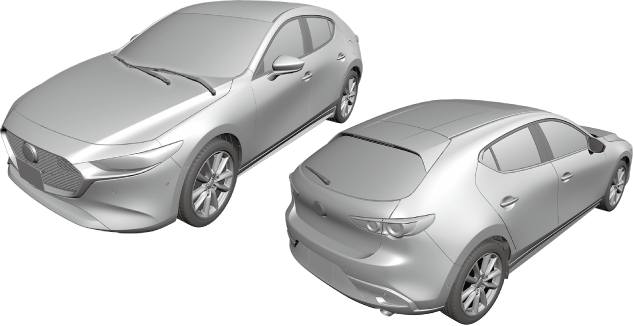
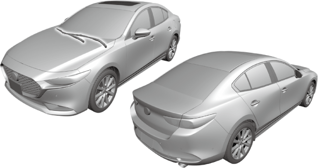
Vehicle Outline
External view
4SD
am3zzn00010048
|
5HB
am3zzn00010049
|
Interior design
am3zzn00006722
|
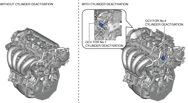
Engine
am3zzn00009074
|
am3zzn00010270
|
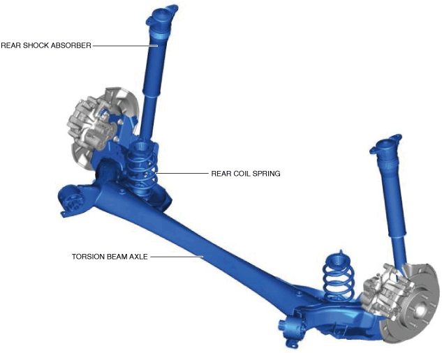
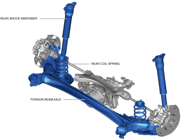
Suspension
am3zzn00010413
|
2WD
am3zzn00006758
|
AWD
am3zzn00009757
|
Driveline/axle
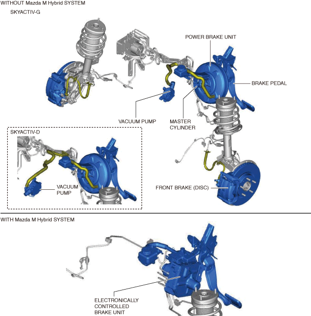
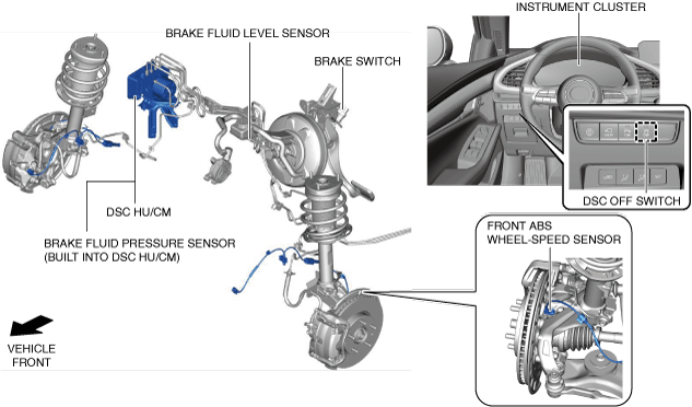
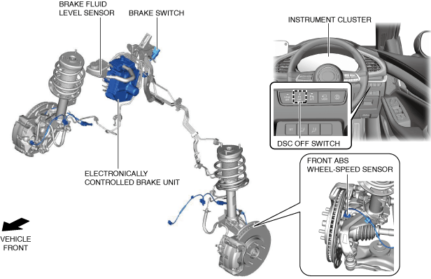
Brakes
Vehicle front side (L.H.D.)
am3zzn00010104
|
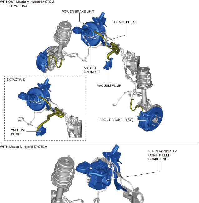
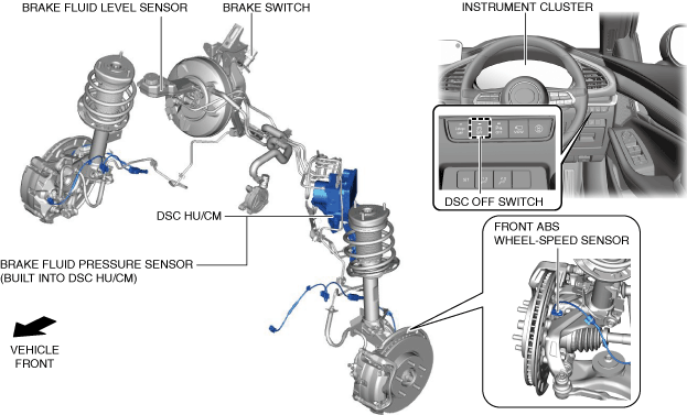
Vehicle front side (R.H.D.)
am3zzn00010105
|
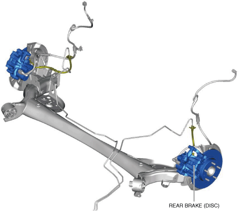
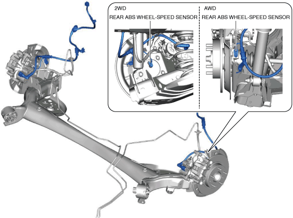
Vehicle rear side
am3zzn00007909
|
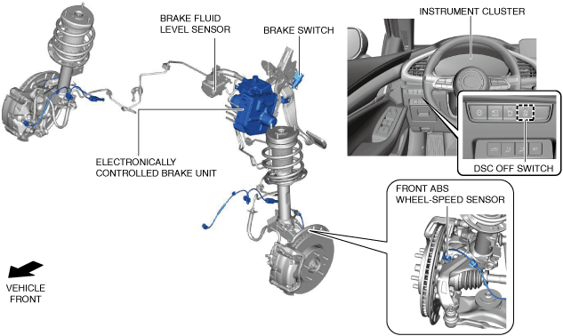
Vehicle front side (L.H.D.)
am3zzn00009805
|
Vehicle front side (R.H.D.)
am3zzn00009859
|
Vehicle rear side
am3zzn00009754
|
Vehicle front side (L.H.D.)
am3zzn00009921
|
Vehicle front side (R.H.D.)
am3zzn00009922
|
Vehicle rear side
am3zzn00009754
|
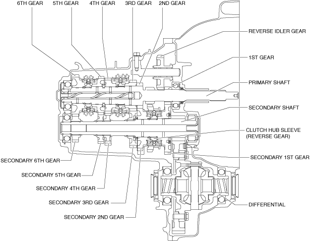
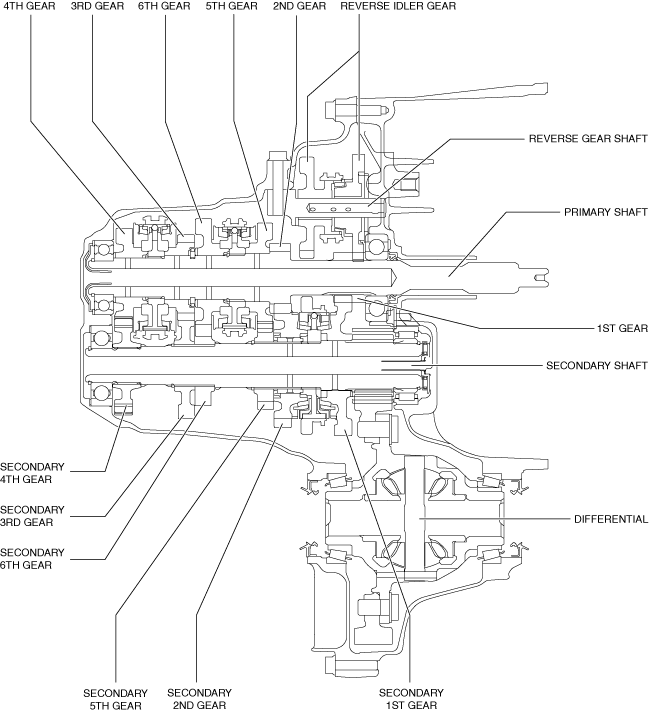
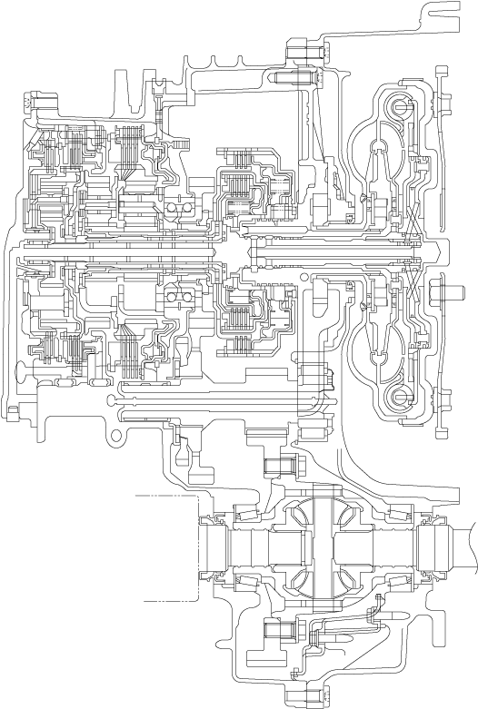
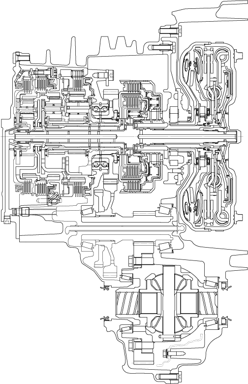
Transaxle
am2zzn00002479
|
am3zzn00006970
|
am2zzn00002190
|
am3zzn00006875
|
am3zzn00009530
|
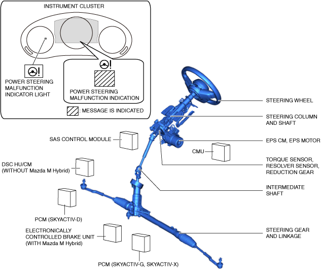
Steering
L.H.D.
am3zzn00010107
|
R.H.D.
am3zzn00010108
|
Heater, ventilation and air conditioning
Restraints
|
Seat position |
Air bag module |
Seat belt |
|||||||
|---|---|---|---|---|---|---|---|---|---|
|
Driver-side air bag module |
Passenger-side air bag module |
Knee air bag module |
Side air bag module |
Curtain air bag module |
ELR (Emergency Locking Retractor) |
Load limiter |
Front pre-tensioner seat belt |
Rear pre-tensioner seat belt |
|
|
Driver's seat
|
×
|
—
|
×
|
×
|
×
|
×
|
×
|
×
|
—
|
|
Passenger's seat
|
—
|
×
|
—
|
×
|
×
|
×
|
×
|
×
|
—
|
|
Rear seat (LH/RH)
|
—
|
—
|
—
|
—
|
×
|
×
|
—
|
—
|
×*
|
|
Rear seat (center)
|
—
|
—
|
—
|
—
|
—
|
×
|
—
|
—
|
—
|
|
Seat position |
Air bag module |
Seat belt |
||||||||
|---|---|---|---|---|---|---|---|---|---|---|
|
Driver-side air bag module |
Passenger-side air bag module |
Knee air bag module |
Side air bag module |
Curtain air bag module |
ELR (Emergency Locking Retractor) |
Load limiter |
ALR (Automatic Locking Retractor) |
Front pre-tensioner seat belt |
Rear pre-tensioner seat belt |
|
|
Driver's seat
|
×
|
—
|
×
|
×
|
×
|
×
|
×
|
—
|
×
|
—
|
|
Passenger's seat
|
—
|
×
|
—
|
×
|
×
|
×
|
×
|
—
|
×
|
—
|
|
Rear seat (LH/RH)
|
—
|
—
|
—
|
—
|
×
|
×
|
×
|
×*
|
—
|
×
|
|
Rear seat (center)
|
—
|
—
|
—
|
—
|
—
|
×
|
—
|
—
|
—
|
—
|
Mazda M Hybrid
i-ACTIVSENSE
|
System
|
Outline
|
Reference
|
|
Mazda Radar Cruise Control (MRCC) system
|
The Mazda radar cruise control (MRCC) system can perform headway control and maintain a constant speed at a set vehicle speed and distance from a vehicle ahead using a front radar sensor and forward sensing camera (FSC) which detects the vehicle ahead without the driver having to depress the accelerator or brake pedal. Additionally, if the detecting vehicle approaches the vehicle ahead too closely such as when the vehicle ahead is braking suddenly, the system alerts the driver using a warning sound and warning indication.
|
|
|
Mazda Radar Cruise Control with stop & go function (MRCC with stop & go function) system
|
The Mazda Radar Cruise Control with Stop & Go function (MRCC with Stop & Go function) uses a front radar sensor and the forward sensing camera (FSC) to detect a vehicle ahead, and performs headway control to maintain a constant distance from a vehicle ahead without the driver having to depress the accelerator or brake pedal. In addition, the detecting vehicle stops when the vehicle ahead stops, and headway control resumes by operating the RES switch/accelerator pedal after the vehicle ahead moves again. This reduces the strain of operating the vehicle such as during long-distance driving, driving at high speeds, and while in heavy traffic. If the detecting vehicle approaches the vehicle ahead too closely such as when the vehicle ahead is braking suddenly, the system alerts the driver using a warning sound and warning indication.
|
|
|
Cruising & Traffic Support (CTS)
|
• The Cruising & Traffic Support (CTS) reduces the strain of operating the vehicle on the highway or motorways using headway control function and steering assist function.
• The Cruising & Traffic Support (CTS) performs vehicle speed control at a constant speed by user setting and headway control to maintain a constant distance from a vehicle ahead without the driver having to depress the accelerator or brake pedal.
• When the detected vehicle ahead stops the monitoring vehicle stop, and headway control resume after the vehicle ahead moves again (Automatic transmission vehicle).
• If the monitoring vehicle approaches the vehicle ahead too closely, the system alerts the driver using a warning sound and warning indication. In addition, the steering assist function assists to help keep the vehicle within the lane lines. If the system does not detect the lane lines, the system assists to help keep the vehicle along the motion path with the vehicle ahead.
|
|
|
Distance & Speed Alert (DSA)
|
The distance & speed alert (DSA) warns the driver using the multi-infomation display based on the calculated time to the vehicle ahead.
|
|
|
Lane-keep assist system
|
• The lane-keep assist system provides steering assistance to help the driver stay within the vehicle lane if the vehicle might be deviating.
• The forward sensing camera (FSC) detects the white lines (yellow lines) of the vehicle lane in which the vehicle is traveling and if the system determines that the vehicle may deviate from its lane, it operates the electric power steering to assist the driver’s steering operation.
|
|
|
Lane Departure Warning System (LDWS)
|
The Lane Departure Warning System (LDWS) recognizes vehicle lane lines on a road using the forward sensing camera (FSC) installed to the windshield, and if the vehicle departs from its lane unknowingly by the driver, the system alerts the driver of the lane departure using a warning indication and warning sound.
|
|
|
Adaptive LED headlights
|
The adaptive LED headlights improve visibility by changing the headlight illumination range depending on the vehicle driving conditions and the surrounding conditions without switching the headlights between HI/LO.
|
|
|
High Beam Control (HBC) System
|
The High Beam Control (HBC) system turns the headlights HI off when the forward sensing camera (FSC) installed to the windshield recognizes a vehicle ahead and when traveling through towns and cities while the vehicle is being driven with the headlights HI turned on. Due to this, blinding of other vehicles from headlight glare is prevented and driver visibility is assured.
|
|
|
Adaptive Front Lighting System (AFS)
|
The adaptive front lighting system (AFS) is a system which enhances the range of visibility when the headlights are turned on by pointing the optical axis of the headlights in the direction in which the vehicle is advancing according to the steering operation.
|
|
|
Blind Spot Monitoring (BSM) system
|
The blind spot monitoring (BSM) system detects vehicles approaching from behind using radar and alerts the driver of the presence of an approaching vehicle. In addition, if the turn switch is operated when a vehicle is approaching from behind, it warns the driver by operating the warnings.
|
|
|
Front Cross Traffic Alert (FCTA) system
|
• The front cross traffic alert (FCTA) is designed to assist the driver in checking both sides of the vehicle when the vehicle starts to drive at an intersection.
• The front cross traffic alert (FCTA) detects vehicle approaching from the blind spots on the front left and right sides of the vehicle when the vehicle starts to drive at an intersection, and notifies the driver of possible danger using the warning indication on the display and the warning sound.
|
|
|
Rear Cross Traffic Alert (RCTA) system
|
The rear cross traffic alert (RCTA) system detects vehicles approaching from behind using radar and alerts the driver of the presence of an approaching vehicle.
|
|
|
Driver Attention Alert system
|
• The driver attention alert system warns the driver using the warning display and sound if it detects the driver's lack of attentiveness.
• The driver attention alert system activates the warning if the driver's attention decreases due to driving long distances for long periods causing the vehicle to sway.
|
|
|
Driver Monitoring (DM)
|
The driver monitoring (DM) detects an action state of the driver (looking away, drowsiness level) by the camera inside the vehicle and the vehicle information. If the system determines dangerous driving (looking away), it ensures the driver safety by warning display, warning sound and start of automatic braking.
|
(See DRIVER MONITORING (DM).)
|
|
Traffic Sign Recognition system (TSR)
|
• The traffic sign recognition system (TSR) provides support for safe driving by displaying traffic signs on the active driving display or by notifying the driver of excessive speed.
• The traffic sign recognition system (TSR) helps prevent accidents caused by overlooking traffic signs by automatically displaying the traffic signs on the active driving display where the driver can easily recognize them.
|
|
|
360°View Monitor system
|
• The 360° view monitor system is technology created from Mazda's safety philosophy stated as the reduction of accident occurrence risk itself, and which is particular to the recognition support function.
• The 360° view monitor system displays the images shot by the four cameras (front camera, side cameras (LH, RH), rear mount camera) equipped to the vehicle at the viewpoints from the front/back, left/right, and above the vehicle on the center display, and supports the driver in recognizing risks in the driver's blind spot areas.
|
(See 360°VIEW MONITOR SYSTEM.)
|
|
Adjustable speed limiter
|
• For the purpose of safety performance improvement, the adjustable speed limiter restricts unintended excess vehicle speed by allowing the driver to optionally set the maximum vehicle speed.
• The adjustable speed limiter restricts the engine output so that the vehicle speed does not exceed the set maximum vehicle speed even if the accelerator pedal is being depressed.
• The adjustabel speed limiter does not operate simultaneously with the cruise control system.
|
|
|
Intelligent Speed Assistance (ISA)
|
The Intelligent Speed Assistance (ISA) is a function which keeps the vehicle speed below the speed limit set from a speed limit sign or an optionally set speed limit. If the vehicle speed exceeds the set speed limit while driving on steep slopes, the system notifies the driver using the display and a warning sound.
|
|
System
|
Outline
|
Reference
|
|
Smart Brake Support (SBS)
|
• The Smart Brake Support (SBS) warns the driver using the warning indication in the active driving display or multi-information display and warning alarm sounds when the front radar sensor, ultrasonic sensor and forward sensing camera (FSC) detect a vehicle ahead, pedestrian or bicycle, and if there is the possibility of a collision.
• If the possibility of a collision increases, it operates the brakes automatically to decrease the damage from the possible collision.
|
(See SMART BRAKE SUPPORT (SBS).)
|
|
Smart Brake Support [Rear] (SBS-R)
|
The Smart Brake Support [Rear] (SBS-R) system is designed to apply the brakes automatically to reduce the damage from a possible collision if the driver fails to confirm the safety at the rear while reversing resulting in an increased possibility of a collision with vehicles or obstructions at the rear of the vehicle.
|
|
|
Smart Brake Support [Rear Crossing] (SBS-RC)
|
The Smart Brake Support [Rear Crossing] (SBS-RC) system is designed to apply the brakes automatically to reduce the damage from a possible collision with vehicles crossing from rear side of the vehicle when the vehicle is reversing to get out of the parking lot.
|