|
1
|
VERIFY EXHAUST COLOR
• What color is smoke coming from the exhaust system?
|
Blue
|
Burning oil is indicated.
• Go to the next step.
|
|
White
|
Water in combustion is indicated.
• Go to Step 4.
|
|
Black
|
Rich fuel mixture is indicated.
• Go to Step 5.
|
|
2
|
INSPECT PCV VALVE FOR MALFUNCTION
• Inspect the applicable part.
• Is the part normal?
|
Yes
|
Go to the next step.
|
|
No
|
Repair or replace the malfunctioning location and perform the repair completion verification.
|
|
3
|
INSPECT ENGINE INTERNAL PARTS
• Inspect for the following engine internal parts:
-
― Damaged valve guide, stems or valve seals
― Blocked oil drain passage in cylinder head
― Piston ring is not seated, seized or worn
― Damage cylinder bore
• Is there any malfunction?
|
Yes
|
Repair or replace the malfunctioning location and perform the repair completion verification.
|
|
No
|
Engine internal parts are normal.
• If other driveability symptoms are present:
-
― Return to the diagnostic index to service additional symptoms.
|
|
4
|
INSPECT ENGINE FOR ENGINE COOLANT LEAKAGE
• Does the cooling system hold the coolant pressure?
|
Yes
|
Inspect the following:
• Cylinder head gasket leakage
• Intake manifold gasket leakage
• Cracked or porous engine block
If there is any malfunction:
• Repair or replace the malfunctioning location and perform the repair completion verification.
If there is no malfunction:
• If other driveability symptoms are present:
-
― Return to the diagnostic index to service additional symptoms.
|
|
No
|
Repair or replace the malfunctioning location and perform the repair completion verification.
|
|
5
|
VERIFY CURRENT INPUT SIGNAL STATUS
-
Warning
-
• While performing this step, always operate the vehicle in a safe and lawful manner.
• When the M-MDS is used to observe monitor system status while driving, be sure to have another technician with you, or record the data in the M-MDS using the PID/DATA MONITOR AND RECORD capturing function and inspect later.
• Access the following PIDs using the M-MDS:
-
― APP1
― APP2
― ECT
― ECT_VOLT
― ECT2
― ECT2_VOLT
― IAT
― MAF
― MAP
― MAP_VOLT
― TP_RELAT
― A/F_SEN_CUR
― HO2S_OUT_VOLT
― SHRT_FUEL_TRIM
― LONG_FUEL_TRIM
• Monitor the PIDs under the black smoke appeared engine condition.
• Do the PIDs indicate normal according to engine conditions?
|
Yes
|
Go to the next step.
|
|
No
|
APP1, APP2 PIDs are not as specified:
• Inspect the APP sensor No.1 and No.2.
ECT, ECT_VOLT, ECT2, ECT2_VOLT PIDs are not as specified:
• Inspect the ECT sensor No.1 and No.2.
IAT PID is not as specified:
• Inspect the IAT sensor No.1.
MAF PID is not as specified:
• Inspect the MAF sensor.
MAP, MAP_VOLT PIDs are not as specified:
• Inspect the MAP sensor.
TP_RELAT PID is not as specified:
A/F_SEN_CUR, SHRT_FUEL_TRIM, LONG_FUEL_TRIM PIDs are not as specified:
• Inspect the A/F sensor.
HO2S_OUT_VOLT PID is not as specified:
Repair or replace the malfunctioning location.
• If the malfunction remains:
-
― Perform the “Action for Non-repeatable Malfunction” procedure.
|
|
6
|
INSPECT FUEL INJECTOR OPERATION
• Perform the Fuel Injector Operation Inspection.
• Do the fuel injectors operate properly?
|
Yes
|
Go to the next step.
|
|
No
|
Repair or replace the malfunctioning location and perform the repair completion verification.
|
|
7
|
INSPECT INTAKE AIR SYSTEM
• Inspect the following for intake-air system:
-
― Air cleaner restriction
― Collapsed or restricted air hose
― Leakage at engine intake manifold
• Is there any malfunction?
|
Yes
|
Repair or replace the malfunctioning location and perform the repair completion verification.
|
|
No
|
Go to the next step.
|
|
8
|
INSPECT EXHAUST SYSTEM FOR LEAKAGE
• Visually inspect for exhaust gas leakage from exhaust manifold.
• Is there any leakage?
|
Yes
|
Repair or replace the malfunctioning location and perform the repair completion verification.
|
|
No
|
Go to the next step.
|
|
9
|
INSPECT FUEL PRESSURE (HIGH-SIDE)
• Start the engine and warm it up completely.
• Access the FUEL_PRES PID using the M-MDS at idle.
• Is the FUEL_PRES PID value within specification?
Specification:
• Approx. 10 MPa {102 kgf/cm2, 1450 psi} (Except Thailand specs.)
• Approx. 3 MPa {31 kgf/cm2, 435 psi} (Thailand specs.)
|
Yes
|
Go to Step 13.
|
|
No
|
Lower than specification:
• Inspect the following:
-
― Fuel leakage at the fuel line and fuel injector
― Fuel pump
-
• Perform the Fuel Pump (Low-pressure Side) Operation Inspection.
― High pressure fuel pump
• If there is any malfunction:
-
― Repair or replace the malfunctioning location and perform the repair completion verification.
• If there is no malfunction:
-
― Go to Step 12.
Higher than specification:
• Go to the next step.
|
|
10
|
DETERMINE IF MALFUNCTION CAUSE IS FUEL PRESSURE SENSOR OR HIGH PRESSURE FUEL PUMP
• Is the vehicle acceleration performance normal?
|
Yes
|
Go to the next step.
|
|
No
|
Go to Step 12.
|
|
11
|
INSPECT FUEL PRESSURE SENSOR FOR MALFUNCTION
• Inspect the applicable part.
• Is the part normal?
|
Yes
|
Go to Step 13.
|
|
No
|
Replace the fuel distributor and perform the repair completion verification.
|
|
12
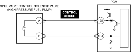
|
INSPECT SPILL VALVE CONTROL SOLENOID VALVE CONTROL CIRCUIT FOR SHORT TO GROUND
• Inspect the applicable circuit for a short to ground.
• Is the circuit normal?
|
Yes
|
Replace the high pressure fuel pump and perform the repair completion verification.
|
|
No
|
Repair or replace the malfunctioning location and perform the repair completion verification.
|
|
13
|
INSPECT FUEL PRESSURE (LOW-SIDE)
• Connect the fuel pressure gauge between fuel pump and high pressure fuel pump.
• Measure the low side fuel pressure.
• Is the low side fuel pressure within specification?
Specification:
• 475—555 kPa {4.85—5.65 kgf/cm2, 68.9—80.4 psi}
|
Yes
|
Go to the next step.
|
|
No
|
Inspect the following:
• Fuel line restriction
• Fuel filter clogged
-
― If there is any malfunction:
-
• Repair or replace the malfunctioning location and perform the repair completion verification.
― If there is no malfunction:
-
• Replace the fuel pump unit and perform the repair completion verification.
|
|
14
|
INSPECT IGNITION SYSTEM OPERATION
-
Note
-
• Because the malfunction may have been resolved by removing the carbon adhered to the spark plug during the spark inspection for the spark plug, verify that the repairs have been completed.
• Perform the Spark Test.
• Is a strong blue spark visible at each cylinder?
|
Yes
|
Go to the next step.
|
|
No
|
Repair or replace the malfunctioning location and perform the repair completion verification.
|
|
15
|
INSPECT ENGINE COMPRESSION
• Measure the compression pressure for each cylinder.
• Are compression pressures within specification?
|
Yes
|
Injector driver malfunction.
If the problem remains, overhaul the engine and perform the repair completion verification.
|
|
No
|
Inspect the following:
• Damaged valve seat
• Worn valve stem and valve guide
• Worn or stuck piston ring
• Worn piston, piston ring or cylinder
• Improper intake valve timing
• Improper exhaust valve timing
Repair or replace the malfunctioning location and perform the repair completion verification.
|
|
Repair completion verification 1
|
VERIFY THAT VEHICLE IS REPAIRED
• Install/connect the part removed/disconnected during the troubleshooting procedure.
• Has the malfunction symptom been eliminated?
|
Yes
|
Complete the symptom troubleshooting. (Explain contents of repair to customer)
|
|
No
|
Refer to the controller area network (CAN) malfunction diagnosis flow to inspect for a CAN communication error.
• If the CAN communication is normal, perform the diagnosis from Step 1.
-
― If the malfunction recurs, go to the next step.
|
|
Repair completion verification 2
|
VERIFY IF MALFUNCTION IS CAUSED BY NOT PERFORMING PCM REPROGRAMMING
• Verify repair information and verify that there is a new calibration in the PCM.
• Is there a new calibration in the PCM?
|
Yes
|
Perform the PCM reprogramming and verify if the malfunction symptom was corrected.
• If the malfunction recurs, replace the PCM.
|
|
No
|
Replace the PCM.
|