AIR CHARGING SYSTEM [SKYACTIV-D 1.8]
id0113q9706400
Purpose, Outline
• The turbocharger system rotates the turbine wheel of the turbocharger with variable turbine geometry using the pressure of the exhaust gas to rotate the compressor wheel on the intake air side on the same axis, and compress the intake air which is then supplied to the engine.
• By equipping the boost system, NOx and particulate matter (PM) are reduced and the exhaust gas is purified.
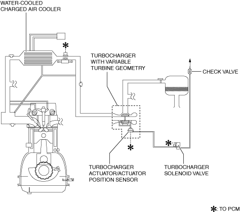
System diagram
Structure
• The air charging system consists of the following parts.
|
Part name
|
Reference
|
|
Turbocharger with variable turbine geometry
|
Turbocharger with variable turbine geometry
|
|
|
Turbocharger actuator
|
|
Actuator position sensor
|
|
|
Turbocharger solenoid valve
|
|
|
Water-cooled charge air cooler
|
|
|
Vacuum chamber (built into cylinder head cover)
|
―
|
|
Check valve
|
―
|
Function
• The turbocharger with variable turbine geometry is structured such that the total volume of exhaust gas passes through the turbine wheel, and the air charging pressure control is performed by the opening and closing of the variable nozzles in the turbocharger with variable turbine geometry.
• The turbo actuator rod operates by the adjustment of turbocharger solenoid valve which occurs by the vacuum generated by the intake manifold and the vacuum in the vacuum chamber generated by vacuum pump. When the rod is pulled by the applied vacuum, the variable nozzle opening angle becomes smaller. When the vacuum is no longer applied, the variable nozzle opening angle becomes larger.
• The intake air charged by the rotation of the compressor wheel is cooled by the water-cooled charge air cooler, and it is supplied to the cylinders under high air-density conditions.
Operation
Increasing boost pressure
-
• Vacuum is applied to the turbocharger actuator to decrease the opening angle of the variable nozzle. By decreasing the opening angle of the variable nozzle, the exhaust gas flow speed increases and the turbine wheel rotation speed increases. Generally, when the engine speed increases and the exhaust gas increases, the opening angle of the variable nozzles gradually increases to flow the exhaust smoothly.
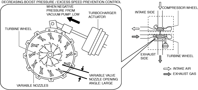
Decreasing boost pressure
-
• Vacuum applied to the turbocharger actuator is released to increases the opening angle of the variable nozzle. By increasing the opening angle of the variable nozzle, the exhaust gas flow speed decreases, the turbine wheel rotation speed decreases, and boost pressure decreases.The opening angle of the variable nozzle may become smaller depending on the opening angle conditions of each EGR system valve and the engine speed.
*1
*1 :The operations of the turbocharger actuator include the operation in conjunction with the desired torque of the driver (accelerator pedal opening angle) and operation in conjunction with the EGR control. For boost control details, refer to the CONTROL SYSTEM. (See
BOOST CONTROL [SKYACTIV-D 1.8].)
Excess speed prevention control
-
• To prevent the turbocharger with variable turbine geometry from operating in excess speed, the opening angle of the variable nozzles and fuel injection amount are controlled so that the turbine speed is the specified value or less.