|
1
|
INSPECT BRAKE FLUID AMOUNT AND VERIFY THAT ELECTRIC PARKING BRAKE RELEASED
• Inspect the brake fluid amount and verify that the electric parking brake released.
• Is the brake fluid amount normal?
• Is the electric parking brake released?
|
Yes
|
Go to the next step.
|
|
No
|
Add the brake fluid or release the electric parking brake.
If the brake fluid refilled:
• Inspect and repair the brake line for leakage.
Perform the repair completion verification.
|
|
2
|
CONFIRM ELECTRONICALLY CONTROLLED BRAKE UNIT DTC
• Retrieve the electronically controlled brake unit DTC using the M-MDS.
• Are any DTCs present?
|
Yes
|
Go to the applicable DTC inspection.
|
|
No
|
If communication error message is displayed on the M-MDS screen:
• Go to the next step.
If communication error message is not displayed:
• Go to Step 4.
|
|
3
|
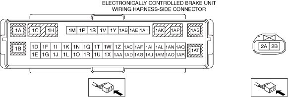
INSPECT CONNECTION OF ELECTRONICALLY CONTROLLED BRAKE UNIT CONNECTOR
• Inspect for connection of the electronically controlled brake unit connector.
• Is the electronically controlled brake unit connector connected securely?
|
Yes
|
Go to the next step.
|
|
No
|
Connect the electronically controlled brake unit connector securely, then go to the next step.
|
|
4
|
CONFIRM INSTRUMENT CLUSTER OPERATION RECORD
• Retrieve the warning system operation history using the M-MDS.
• Is the brake system warning light illumination history recorded?
|
Yes
|
If the Brake Waning Lamp recorded:
• Go to Step 5.
If the Brake Waning Lamp (Brake fluid low) recorded:
• Go to Step 6.
|
|
No
|
Go to Step 8.
|
|
5
|
VERIFY WHETHER MALFUNCTION IS IN INSTRUMENT CLUSTER OR ELSEWHERE
• Connect the M-MDS to the DLC-2.
• Ignition is switched ON (engine off).
• Do the ABS warning light, brake system warning light, DSC indicator light and DSC OFF indicator light turn on and off according to the simulation?
|
Yes
|
Go to Step 8.
|
|
No
|
Replace the instrument cluster, and perform the repair completion verification.
|
|
6
|
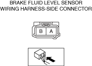
INSPECT WHETHER MALFUNCTION IS IN BRAKE FLUID LEVEL SENSOR OR ELSEWHERE
• Inspect the brake fluid level sensor.
• Is the continuity condition normal?
|
Yes
|
Go to the next step.
|
|
No
|
Replace the malfunctioning part, and perform the repair completion verification.
|
|
*7
|
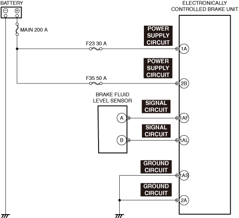
INSPECT BRAKE FLUID LEVEL SENSOR SIGNAL CIRCUIT FOR SHORT TO GROUND
• Inspect the signal circuit for a short to ground.
• Is the circuit normal?
|
Yes
|
Retrieve the electronically controlled brake unit DTC using the M-MDS.
If the DTC remains:
• Go to the applicable DTC inspection.
If the DTC does not remain:
• Replace the electronically controlled brake unit.
|
|
No
|
Repair or replace the malfunctioning location, and perform the repair completion verification.
|
|
*8
|
INSPECT ELECTRONICALLY CONTROLLED BRAKE UNIT POWER SUPPLY CIRCUIT FOR SHORT TO GROUND AND OPEN CIRCUIT
• Inspect the power supply circuit for an open circuit and short to ground.
• Is the circuit normal?
|
Yes
|
Go to the next step.
|
|
No
|
Repair or replace the malfunctioning location, and perform the repair completion verification.
|
|
*9
|
INSPECT ELECTRONICALLY CONTROLLED BRAKE UNIT GROUND CIRCUIT FOR SHORT TO POWER SUPPLY AND OPEN CIRCUIT
• Inspect the ground circuit for an open circuit and short to power supply.
• Is the circuit normal?
|
Yes
|
Replace the electronically controlled brake unit, and perform the repair completion verification. (open circuit in the electronically controlled brake unit)
|
|
No
|
Repair or replace the malfunctioning location, and perform the repair completion verification.
|
|
Repair completion verification
|
VERIFY THAT MALFUNCTION SYMPTOMS DO NOT RECUR AFTER REPAIR
• Install/connect the part removed/disconnected during the troubleshooting procedure.
• Has the malfunction symptom been eliminated?
|
Yes
|
Complete the symptom troubleshooting.
Explain to the customer what has been repaired.
|
|
No
|
Refer to the controller area network (CAN) malfunction diagnosis flow to inspect for a CAN communication error.
If the CAN communication is normal, perform the diagnosis from Step 1.
|