 |
am3zzw00035164
SHIFT CONTROL MODULE REMOVAL/INSTALLATION [C66M-R, C66MX-R]
id0515ma160200
Replacement Part
|
Gasket
Quantity: 1
Location of use: Detent ball pin
|
Breather
Quantity: 1
Location of use: Shift control module
|
O-ring
Quantity: 1
Location of use: Shift control module
|
1. Shift the shift lever to the neutral position.
2. Disconnect the negative battery terminal. (See NEGATIVE BATTERY TERMINAL DISCONNECTION/CONNECTION [(E)].)
3. Open the engine cover. (SKYACTIV-X 2.0) (See ENGINE COVER OPEN/CLOSE [SKYACTIV-X 2.0].)
4. Remove the following parts as a single unit. (See INTAKE-AIR SYSTEM REMOVAL/INSTALLATION [SKYACTIV-G (WITHOUT CYLINDER DEACTIVATION (E))].) (See INTAKE-AIR SYSTEM REMOVAL/INSTALLATION [SKYACTIV-G (WITH CYLINDER DEACTIVATION (E))].) (See INTAKE-AIR SYSTEM REMOVAL/INSTALLATION [SKYACTIV-D 1.8].) (See AIR CLEANER REMOVAL/INSTALLATION [SKYACTIV-X 2.0].)
5. Remove the resonance chamber (SKYACTIV-X 2.0) (See AIR CLEANER REMOVAL/INSTALLATION [SKYACTIV-X 2.0].)
6. Remove the battery. (See BATTERY REMOVAL/INSTALLATION [SKYACTIV-G (WITHOUT CYLINDER DEACTIVATION (E))].) (See BATTERY REMOVAL/INSTALLATION [SKYACTIV-G (WITH CYLINDER DEACTIVATION (E))].) (See BATTERY REMOVAL/INSTALLATION [SKYACTIV-D 1.8].) (See BATTERY REMOVAL/INSTALLATION [SKYACTIV-X 2.0].)
7. Remove the battery tray and PCM component as a single unit. (Except SKYACTIV-D 1.8) (See BATTERY REMOVAL/INSTALLATION [SKYACTIV-G (WITHOUT CYLINDER DEACTIVATION (E))].) (See BATTERY REMOVAL/INSTALLATION [SKYACTIV-G (WITH CYLINDER DEACTIVATION (E))].) (See BATTERY REMOVAL/INSTALLATION [SKYACTIV-X 2.0].)
8. Remove the battery tray. (SKYACTIV-D 1.8) (See BATTERY REMOVAL/INSTALLATION [SKYACTIV-D 1.8].)
9. Disconnect the control cable from the manual transaxle. (See CONTROL CABLE REMOVAL/INSTALLATION [C66M-R, C66MX-R].)
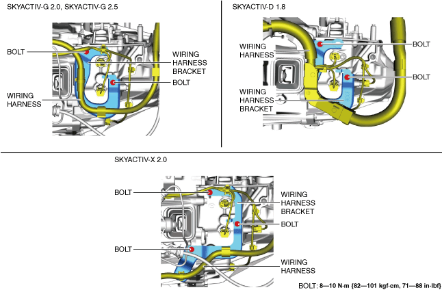
10. Remove the bolts and set the wiring harness and wiring harness bracket in a place which does not interfere with servicing.
am3zzw00035164
|
11. Remove the neutral sensor No.1. (See NEUTRAL SENSOR REMOVAL/INSTALLATION [C66M-R, C66MX-R].)
12. Remove the neutral sensor No.2. (with i-stop) (See NEUTRAL SENSOR REMOVAL/INSTALLATION [C66M-R, C66MX-R].)
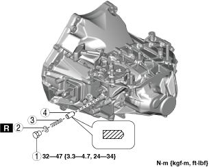
13. Remove the detent ball pin in the order shown in the figure.
am3zzw00021728
|
|
1
|
Plug
|
|
2
|
Gasket
|
|
3
|
Spring
|
|
4
|
Detent ball pin
|
14. Remove the back-up light switch. (See BACK-UP LIGHT SWITCH REMOVAL/INSTALLATION [C66M-R, C66MX-R].)
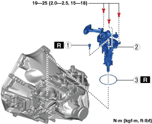
15. Remove the shift control module in the order shown in the figure.
am3zzw00021729
|
|
1
|
Breather
|
|
2
|
Shift control module
|
|
3
|
O-ring
|
16. Install in the reverse order of removal.
Shift Control Module Installation Note
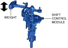
1. Verify that the shift control module is in the neutral position.
am3zzw00021730
|
2. Install the shift control module.
Control Cable Ends (Transaxle Side) Installation Note
1. Verify that the shift control module is in the neutral position.
2. Connect the control cable to the manual transaxle. (See CONTROL CABLE REMOVAL/INSTALLATION [C66M-R, C66MX-R].)
3. Verify that the shift lever on the cabin side operates smoothly.