|
1
|
VERIFY ALL SYSTEM DTCs
• Perform the DTC inspection.
• Are any DTCs displayed?
|
Yes
|
Repair the malfunctioning location according to the applicable DTC troubleshooting.
|
|
No
|
Go to the next step.
|
|
2
|
VERIFY THAT OPERATION INDICATOR LIGHT TURNS ON WHEN REMOTE TRANSMITTER BUTTON IS USED
• Does the operation indicator light turn on?
|
Yes
|
Go to Step 5.
|
|
No
|
Go to the next step.
|
|
3
|
VERIFY IF PROBLEM IS DUE TO REMOTE TRANSMITTER POWER SAVING FUNCTION
• Turn off the power saving function by the following operation.
-
1. Press the lock button on the transmitter 4 times within 3 seconds to turn on the operation indicator light.
2. Press the lock button continuously for 1.5 seconds or longer while the operation indicator light turns on (for 5 seconds).
• Does the operation indicator light turn on?
|
Yes
|
Perform the repair completion verification.
|
|
No
|
Go to the next step.
|
|
4
|
VERIFY BATTERY USED FOR REMOTE TRANSMITTER
• Is any of the following conditions met?
-
― Battery other than CR2032 is used
― Battery is inserted in opposite direction
― Battery voltage is low
|
Yes
|
Replace the remote transmitter battery and perform the repair completion verification.
|
|
No
|
Replace the remote transmitter and perform the repair completion verification.
|
|
5
|
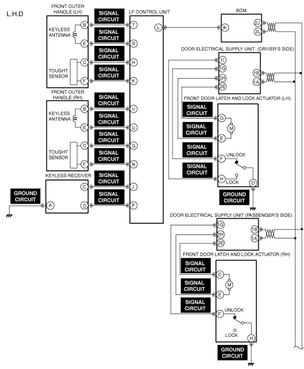
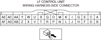
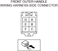
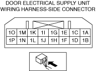
INSPECT FRONT OUTER HANDLE, KEYLESS RECEIVER, LF CONTROL UNIT, BCM, DOOR-ELECTRICAL SUPPLY UNIT, AND FRONT DOOR LATCH AND LOCK ACTUATOR CONNECTORS FOR MALFUNCTION
• Inspect the applicable connector and terminal.
• Is the signal circuit normal?
|
Yes
|
Go to the next step.
|
|
No
|
Repair or replace the malfunctioning location and perform the repair completion verification.
|
|
6
|
INSPECT FRONT OUTER HANDLE SIGNAL CIRCUIT FOR SHORT TO GROUND AND OPEN CIRCUIT
• Inspect the signal circuit for a short to ground and open circuit.
• Is the circuit normal?
|
Yes
|
Go to the next step.
|
|
No
|
Repair or replace the malfunctioning location and perform the repair completion verification.
|
|
7
|
INSPECT KEYLESS RECEIVER SIGNAL CIRCUIT FOR SHORT TO GROUND AND OPEN CIRCUIT
• Inspect the signal circuit for a short to ground and open circuit.
• Is the circuit normal?
|
Yes
|
Go to the next step.
|
|
No
|
Repair or replace the malfunctioning location and perform the repair completion verification.
|
|
8
|
INSPECT KEYLESS RECEIVER GROUND CIRCUIT FOR OPEN CIRCUIT
• Inspect the ground circuit for open circuit.
• Is the circuit normal?
|
Yes
|
Go to the next step.
|
|
No
|
Repair or replace the malfunctioning location and perform the repair completion verification.
|
|
9
|
INSPECT FRONT OUTER HANDLE FOR MALFUNCTION
• Inspect the applicable part.
• Is the part normal?
|
Yes
|
Go to the next step.
|
|
No
|
Repair or replace the malfunctioning location and perform the repair completion verification.
|
|
10
|
INSPECT KEYLESS RECEIVER FOR MALFUNCTION
• Inspect the applicable part.
• Is the part normal?
|
Yes
|
Go to the next step.
|
|
No
|
Repair or replace the malfunctioning location and perform the repair completion verification.
|
|
11
|
INSPECT FRONT DOOR LATCH AND LOCK ACTUATOR FOR MALFUNCTION
• Inspect the applicable part.
• Is the part normal?
|
Yes
|
Go to the next step.
|
|
No
|
Repair or replace the malfunctioning location and perform the repair completion verification.
|
|
12
|
INSPECT LF CONTROL UNIT FOR MALFUNCTION
• Inspect the applicable part.
• Is the part normal?
|
Yes
|
Go to the next step.
|
|
No
|
Repair or replace the malfunctioning location and perform the repair completion verification.
|
|
Repair completion verification
|
VERIFY THAT VEHICLE IS REPAIRED
• Install/connect the part removed/disconnected during the troubleshooting procedure.
• Has the malfunction symptom been eliminated?
|
Yes
|
Complete the symptom troubleshooting. (Explain contents of repair to customer)
|
|
No
|
Refer to the controller area network (CAN) malfunction diagnosis flow to inspect for a CAN communication error.
If the CAN communication is normal, perform the diagnosis from Step 1.
• If the malfunction is not resolved, replace the door-electrical supply unit.
|