1. : Mazda SST number
2. : Global SST number
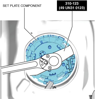
1: 49 UN31 0123
2: 310–123
wrench

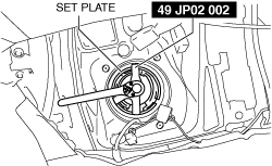
1: 49 JP02 002
2: –
Lock ring wrench

FUEL GAUGE SENDER UNIT REMOVAL/INSTALLATION [(E)]
id0922000120x2
Special Service Tool (SST)
|
1. : Mazda SST number
2. : Global SST number
|
|||
|
1: 49 UN31 0123
2: 310–123
wrench
|
|
1: 49 JP02 002
2: –
Lock ring wrench
|
|
Replacement part
|
Packing
Quantity: 1
Location of use: Fuel gauge sender unit (main (SKYACTIV-D))
|
Packing
Quantity: 1
Location of use: Fuel gauge sender unit (sub)
|
Retainer
Quantity: 1
Location of use: Quick Release Connector (sub)
|
Oil and Chemical Type
|
Engine oil
Type: Recommended oil
|
Fuel Gauge Sender Unit (Main)
SKYACTIV-G, SKYACTIV-X
SKYACTIV-D
1. Complete the “BEFORE SERVICE PRECAUTION”. (See BEFORE SERVICE PRECAUTION [SKYACTIV-D 1.8].)
2. Disconnect the negative battery terminal. (See NEGATIVE BATTERY TERMINAL DISCONNECTION/CONNECTION [(E)].)
3. Remove the rear seat cushion. (See REAR SEAT CUSHION REMOVAL/INSTALLATION.)
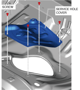
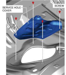
4. Remove the screws.
am3zzw00021182
|
5. Remove the service hole cover.
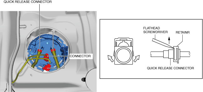
6. Disconnect the connector.
am3zzw00029525
|
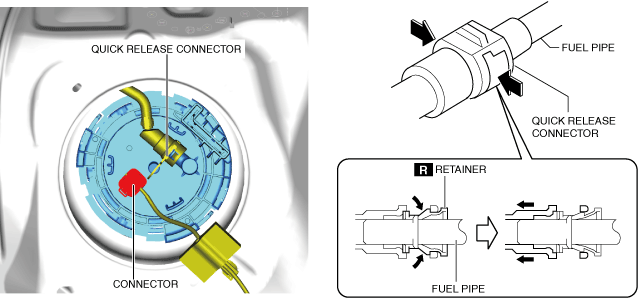
7. Move the retainer upward using a small flathead screwdriver or a similar tool.
8. Pull out the fuel hose straight from the fuel pipe and disconnect it. (SeeQuick release connector assembly note (fuel gauge sender unit (main)).)
9. Install the SST shown in the figure.
am3zzw00029526
|
10. Remove the set plate component using the SST. (See Set plate component installation note (main).)
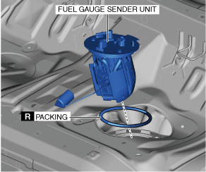
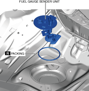
11. Remove the fuel gauge sender unit and packing.
am3zzw00035393
|
12. Install in the reverse order of removal.
13. Complete the “AFTER SERVICE PRECAUTION”. (See AFTER SERVICE PRECAUTION [SKYACTIV-D 1.8].)
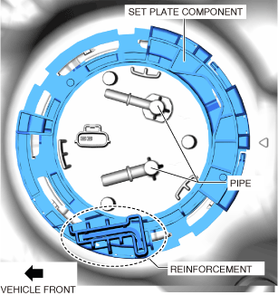
Set plate component installation note (main)
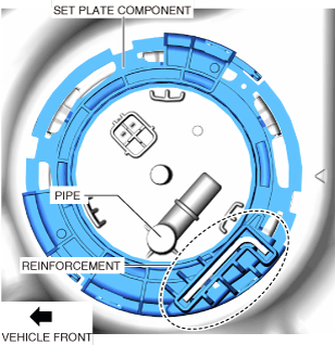
1. Align the reinforcement part of the set plate component near the pipe area of the fuel pump unit as shown in the figure and assemble.
ac30zw00003110
|
Quick release connector assembly note (fuel gauge sender unit (main))
1. Inspect the fuel hose and fuel pipe sealing surface for damage and deformation.
2. Install the quick release connector.
am6zzw00013722
|
3. Lightly pull and push the quick release connector a few times by hand, and then verify that it is connected securely.
4. Perform the fuel leakage inspection referring to “AFTER SERVICE PRECAUTION”. (See AFTER SERVICE PRECAUTION [SKYACTIV-D 1.8].)
Fuel Gauge Sender Unit (Sub)
1. Complete the “BEFORE SERVICE PRECAUTION”. (See BEFORE SERVICE PRECAUTION [SKYACTIV-X 2.0].)
2. Disconnect the negative battery terminal. (See NEGATIVE BATTERY TERMINAL DISCONNECTION/CONNECTION [(E)].)
3. Remove the rear seat cushion. (See REAR SEAT CUSHION REMOVAL/INSTALLATION.)
4. Remove the screws.
am3zzw00031789
|
5. Remove the service hole cover.
6. Disconnect the connector.
7. Set the finger parallel to the quick release connector.
am3zzw00035551
|
8. Hold the center of the retainer tabs with the finger and press the retainer.
9. Pull the connector side and disconnect the quick release connector.(See Quick release connector assembly note (fuel gauge sender unit (sub)).)
10. Install the SST shown in the figure.
am3zzw00036847
|
11. Remove the set plate component using the SST. (See Set plate component installation note (fuel gauge sender unit (sub)).)
12. Remove the fuel gauge sender unit and packing.
am3zzw00031792
|
13. Install in the reverse order of removal.
14. Complete the “AFTER SERVICE PRECAUTION”. (See AFTER SERVICE PRECAUTION [SKYACTIV-X 2.0].)
Set plate component installation note (fuel gauge sender unit (sub))
1. Align the reinforcement part of the set plate component near the pipe area of the fuel pump unit as shown in the figure and assemble.
ac30zw00003109
|
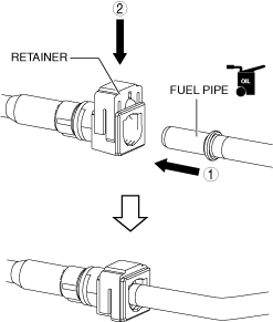
Quick release connector assembly note (fuel gauge sender unit (sub))
am3uuw00005195
|
1. Inspect the fuel hose and fuel pipe sealing surface for damage and deformation.
2. Apply a small amount of clean engine oil to the sealing surface of the fuel pipe.
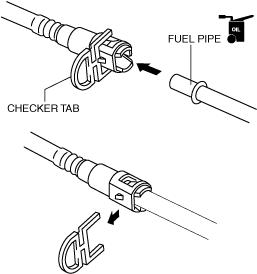
3. Install a new retainer to the quick release connector.
4. Reconnect the fuel hose straight to the fuel pipe until a click is heard.
5. Lightly pull and push the quick release connector a few times by hand, and then verify that it is connected securely.