|
1
|
INSPECT EFFECT OF NON-GENUINE ELECTRICAL ACCESSORY FOR CAUSE OF MALFUNCTION
• Remove any non-genuine electrical accessory.
• Verify the malfunction symptom.
• Is the frequency of the engine restarting from the i-stop off condition the same as that of another vehicle of the same model?
|
Yes
|
The system is normal.
• Explain to the customer that the frequency of the engine restarting increases due to the effect of the non-genuine electrical accessory installed.
|
|
No
|
Go to the next step.
|
|
2
|
VERIFY DTC
• Perform the DTC inspection for the following modules.
-
― PCM
― TCM (ATX)
― DSC HU/CM
― Dash-electrical supply unit
― Body control module (BCM)
• Are any DTCs displayed?
|
Yes
|
Repair the malfunctioning location according to the applicable DTC troubleshooting.
|
|
No
|
Go to the next step.
|
|
3
|
INSPECT BATTERY FOR MALFUNCTION
• Inspect the applicable part.
• Is the part normal?
|
Yes
|
Go to the next step.
|
|
No
|
Repair or replace the malfunctioning location and perform the repair completion verification 1.
|
|
4
|
INSPECT GENERATOR FOR MALFUNCTION
• Inspect the applicable part.
• Is the part normal?
|
Yes
|
Go to the next step.
|
|
No
|
Repair or replace the malfunctioning location and perform the repair completion verification 1.
|
|
5
|
DETERMINE IF MALFUNCTION CAUSE IS STEERING ANGLE SENSOR SIGNAL OR OTHER
• Start the engine and let it idle.
• Access the EPS control module PID STR_ANG using the M-MDS.
• Is the PID value normal?
|
Yes
|
Go to Step 8.
|
|
No
|
Go to the next step.
|
|
6
|
INSPECT STEERING ANGLE SENSOR FOR MALFUNCTION
• Inspect the applicable part.
• Is the part normal?
|
Yes
|
Go to the next step.
|
|
No
|
Repair or replace the malfunctioning location and perform the repair completion verification 1.
|
|
7
|
INSPECT EPS CONTROL MODULE FOR MALFUNCTION
• Inspect the applicable part.
• Is the part normal?
|
Yes
|
Perform the following procedure:
1. Switch the ignition off, and after 2 min or more have elapsed, switch the ignition ON.
2. Start the engine and drive the vehicle 10 m {32 ft 10 in} or more in a straight line at a speed of 10 km/h {6.2 mph} or more.
3. Stop the vehicle with the wheels in the straight-ahead position.
4. Access the EPS control module PID STR_ANG using the M-MDS.
-
• If the STR_ANG value is normal, perform the repair completion verification 1. (Because the steering angle (estimated absolute angle) has returned to normal)
• If the STR_ANG value is not normal, replace the EPS control module, then perform the repair completion verification 1.
|
|
No
|
Repair or replace the malfunctioning location and perform the repair completion verification 1.
|
|
8
|
DETERMINE IF MALFUNCTION CAUSE IS POWER BRAKE UNIT VACUUM SENSOR SIGNAL OR OTHER
• Put the vehicle in an i-stop condition (engine stopped).
• Access the PCM PID BRK_BSTR_PRES_ACT using the M-MDS with the brake pedal depressed and the engine stopped.
• Does the BRK_BSTR_PRES_ACT PID value remain less than -45 kPa {-0.46 kgf/cm2, -6.5 psi}?
|
Yes
|
Go to Step 12.
|
|
No
|
Go to the next step.
|
|
9
|
INSPECT POWER BRAKE UNIT VACUUM SENSOR FOR AIR TIGHTNESS MALFUNCTION
• Perform the vacuum function inspection for the power brake unit and the vacuum loss inspection.
• Is there any malfunction?
|
Yes
|
Repair or replace the malfunctioning location and perform the repair completion verification 1.
|
|
No
|
Go to the next step.
|
|
10
|
INSPECT POWER BRAKE UNIT VACUUM SENSOR FOR MALFUNCTION
• Inspect the applicable part.
• Is the part normal?
|
Yes
|
Go to the next step.
|
|
No
|
Repair or replace the malfunctioning location and perform the repair completion verification 1.
|
|
11
|
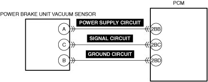
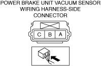
INSPECT POWER BRAKE UNIT VACUUM SENSOR POWER SUPPLY CIRCUIT, SIGNAL CIRCUIT, AND GROUND CIRCUIT FOR SHORT CIRCUIT AND OPEN CIRCUIT
• Inspect the applicable circuit for a short circuit and open circuit.
• Is the circuit normal?
|
Yes
|
Perform the repair completion verification 1.
|
|
No
|
Repair or replace the malfunctioning location and perform the repair completion verification 1.
|
|
12
|
INSPECT DRIVER-SIDE AIR MIX ACTUATOR FOR MALFUNCTION
• Inspect the applicable part.
• Is the part normal?
|
Yes
|
Inspect the air mix door and linkage for sticking.
If there is no malfunction:
• Go to the next step.
If there is any malfunction:
• Repair or replace the malfunctioning location and perform the repair completion verification 1.
|
|
No
|
Repair or replace the malfunctioning location and perform the repair completion verification 1.
|
|
13
|
DETERMINE IF MALFUNCTION CAUSE IS BRAKE FLUID PRESSURE SENSOR SIGNAL OR OTHER
• Put the vehicle in an i-stop condition (engine stopped).
• Monitor the DSC HU/CM PID BRK_FLD_PRES using the M-MDS while the brake is depressed and held with the i-stop function operating.
• Does the monitoring value change?
|
Yes
|
ATX:
• Perform the repair completion verification 1.
MTX:
• Go to the next step.
|
|
No
|
Brake fluid pressure sensor malfunction.
• Replace the DSC HU/CM, then perform the repair completion verification 1.
|
|
14*
|
DETERMINE IF MALFUNCTION CAUSE IS CLUTCH STROKE SENSOR SIGNAL OR OTHER
• Switch the ignition ON (engine off).
• Access the PCM PID CLTCH_PEDAL_POS using the M-MDS.
• Does the CLTCH_PEDAL_POS PID value change according to the amount the clutch pedal is depressed?
|
Yes
|
Perform the repair completion verification 1.
|
|
No
|
Go to the next step.
|
|
15
|
INSPECT CLUTCH STROKE SENSOR FOR MALFUNCTION
• Inspect the applicable part.
• Is the part normal?
|
Yes
|
Go to the next step.
|
|
No
|
Repair or replace the malfunctioning location and perform the repair completion verification 1.
|
|
16
|
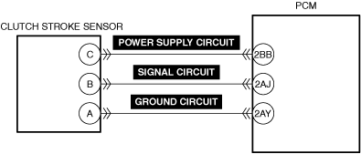
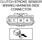
INSPECT CLUTCH STROKE SENSOR SIGNAL CIRCUIT FOR SHORT TO POWER SUPPLY
• Inspect the applicable circuit for a short to power supply.
• Is the circuit normal?
|
Yes
|
Go to the next step.
|
|
No
|
Repair or replace the malfunctioning location and perform the repair completion verification 1.
|
|
Repair completion verification 1
|
VERIFY THAT VEHICLE IS REPAIRED
• Install/connect the part removed/disconnected during the troubleshooting procedure.
• Has the malfunction symptom been eliminated?
|
Yes
|
Complete the symptom troubleshooting. (Explain contents of repair to customer)
|
|
No
|
Refer to the controller area network (CAN) malfunction diagnosis flow to inspect for a CAN communication error.
• If the CAN communication is normal, perform the diagnosis from Step 1.
-
― If the malfunction recurs, go to the next step.
|
|
Repair completion verification 2
|
VERIFY IF MALFUNCTION IS CAUSED BY NOT PERFORMING PCM REPROGRAMMING
• Verify repair information and verify that there is a new calibration in the PCM.
• Is there a new calibration in the PCM?
|
Yes
|
Perform the PCM reprogramming and verify if the malfunction symptom was corrected.
• If the malfunction recurs, replace the PCM.
|
|
No
|
Replace the PCM.
|