|
1
|
INSPECT VEHICLE CONTROL MODULE (VCM) AND BODY CONTROL MODULE (BCM) FOR MALFUNCTION
• Perform the DTC inspection for the vehicle control module (VCM) and the body control module (BCM).
• Is a DTC related to an internal malfunction displayed?
|
Yes
|
Repair the malfunctioning location according to the applicable DTC troubleshooting.
|
|
No
|
Go to the next step.
|
|
2
|
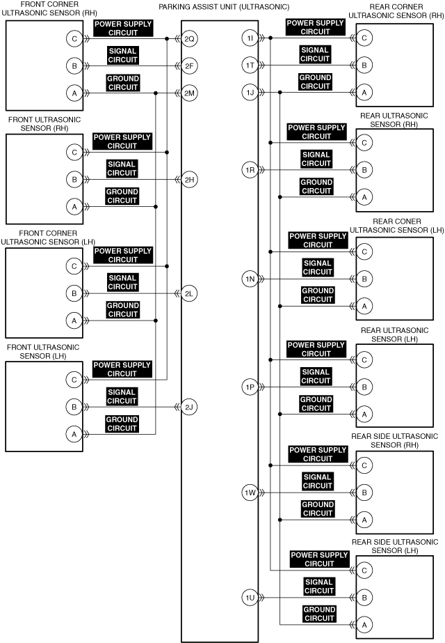
INSPECT PARKING ASSIST UNIT (ULTRASONIC) FOR MALFUNCTION
• Perform the DTC inspection for the parking assist unit (ultrasonic).
• Is a DTC displayed?
|
Yes
|
Repair the malfunctioning location according to the applicable DTC troubleshooting.
|
|
No
|
Go to the next step.
|
|
3
|
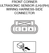
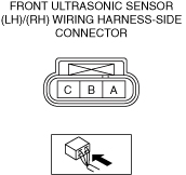
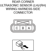
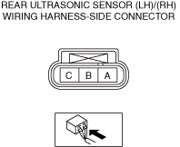
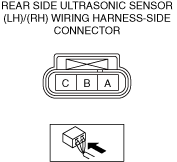
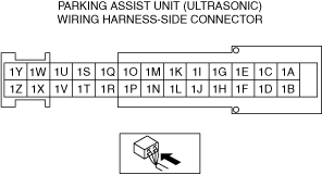
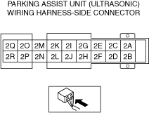
INSPECT EACH ULTRASONIC SENSOR CONNECTOR FOR MALFUNCTION
• Inspect the applicable connector and terminal.
• Are the connector and terminal normal?
|
Yes
|
Go to the next step.
|
|
No
|
Repair or replace the malfunctioning location and perform the repair completion verification 1.
|
|
4
|
INSPECT EACH ULTRASONIC SENSOR POWER SUPPLY CIRCUIT FOR OPEN CIRCUIT
• Inspect the applicable circuit for open circuit.
• Is the circuit normal?
|
Yes
|
Go to the next step.
|
|
No
|
Repair or replace the malfunctioning location and perform the repair completion verification 1.
|
|
5
|
INSPECT EACH ULTRASONIC SENSOR POWER SUPPLY CIRCUIT FOR SHORT TO GROUND
• Inspect the applicable circuit for a short to ground.
• Is the circuit normal?
|
Yes
|
Go to the next step.
|
|
No
|
Repair or replace the malfunctioning location and perform the repair completion verification 1.
|
|
6
|
INSPECT EACH ULTRASONIC SENSOR SIGNAL CIRCUIT FOR OPEN CIRCUIT
• Inspect the applicable circuit for open circuit.
• Is the circuit normal?
|
Yes
|
Go to the next step.
|
|
No
|
Repair or replace the malfunctioning location and perform the repair completion verification 1.
|
|
7
|
INSPECT EACH ULTRASONIC SENSOR SIGNAL CIRCUIT FOR SHORT TO GROUND
• Inspect the applicable circuit for a short to ground.
• Is the circuit normal?
|
Yes
|
Go to the next step.
|
|
No
|
Repair or replace the malfunctioning location and perform the repair completion verification 1.
|
|
8
|
INSPECT EACH ULTRASONIC SENSOR GROUND CIRCUIT FOR OPEN CIRCUIT
• Inspect the applicable circuit for open circuit.
• Is the circuit normal?
|
Yes
|
Go to the next step.
|
|
No
|
Repair or replace the malfunctioning location and perform the repair completion verification 1.
|
|
9
|
INSPECT EACH ULTRASONIC SENSOR FOR MALFUNCTION
• Connect the parking assist unit (ultrasonic) connector.
• Perform the following procedure for each ultrasonic sensor.
-
1. Disconnect the negative battery terminal.
2. If there is a connected ultrasonic sensor connector, disconnect it.
3. Connect any one of each ultrasonic sensor connector.
4. Connect the negative battery terminal.
5. Clear the DTC recorded in the memory.
6. Perform the DTC inspection for the vehicle control module (VCM).
7. Verify if the same DTC is displayed.
• Is the same DTC displayed for all the sensors?
|
Yes
|
Repair the malfunctioning location according to the applicable DTC troubleshooting.
|
|
No
|
Repair or replace the sensor connected when the DTC is displayed, and perform the repair completion verification 1.
|
|
10
|
INSPECT PARKING ASSIST UNIT (ULTRASONIC) FOR MALFUNCTION DEPENDING ON REPEATABILITY
• Install/connect the part removed/disconnected during the troubleshooting procedure.
• Clear the DTC recorded in the memory.
• Perform the DTC inspection for the vehicle control module (VCM).
• Is the same Pending DTC present?
|
Yes
|
Refer to the controller area network (CAN) malfunction diagnosis flow to inspect for a CAN communication error.
If the CAN communication is normal, replace the parking assist unit (ultrasonic) and perform the repair completion verification.
|
|
No
|
Perform the [ACTION FOR NON-REPEATABLE MALFUNCTIONS].
If DTC is displayed
• Repeat the diagnosis from Step 1.
If DTC is not displayed
• Go to repair completion verification 2.
|
|
Repair completion verification 1
|
VERIFY THAT VEHICLE IS REPAIRED
• Install/connect the part removed/disconnected during the troubleshooting procedure.
• Clear the DTC recorded in the memory.
• Perform the DTC inspection for the vehicle control module (VCM).
• Is the same Pending DTC present?
|
Yes
|
Refer to the controller area network (CAN) malfunction diagnosis flow to inspect for a CAN communication error.
If the CAN communication is normal, perform the diagnosis from Step 1.
• If the malfunction recurs, replace the body control module (BCM), then go to the next step.
|
|
No
|
Go to the next step.
|
|
Repair completion verification 2
|
VERIFY IF OTHER DTC IS DISPLAYED
• Perform the DTC inspection.
• Are any other DTCs displayed?
|
Yes
|
Repair the malfunctioning location according to the applicable DTC troubleshooting.
|
|
No
|
DTC troubleshooting completed.
|