|
1
|
VERIFY REAR SIDE RADAR SENSOR INSTALLATION CONDITION
• When a malfunction occurred, verify if the vehicle or environment corresponds to any of the following.
-
― Poor installation, damage, deformity, or looseness of rear side radar sensor bracket, rear bumper (including moderate impacts)
• Did the vehicle or environment correspond to any of the above conditions?
|
Yes
|
Repair or replace the malfunctioning location and perform the repair completion verification.
|
|
No
|
Go to the next step.
|
|
2
|
VERIFY ALL SYSTEM DTCs
• Perform the DTC inspection.
• Are any DTCs displayed?
|
Yes
|
Repair the malfunctioning location according to the applicable DTC troubleshooting.
|
|
No
|
Go to the next step.
|
|
3
|
INSPECT DOOR-ELECTRICAL SUPPLY UNIT AND POWER OUTER MIRROR CONNECTORS FOR MALFUNCTION
• Inspect the applicable connector and terminal.
• Are the connector and terminal normal?
|
Yes
|
Go to the next step.
|
|
No
|
Repair or replace the malfunctioning location and perform the repair completion verification.
|
|
4
|
INSPECT BLIND SPOT MONITORING (BSM) WARNING INDICATOR LIGHT POWER SUPPLY CIRCUIT FOR SHORT TO POWER SUPPLY
• Inspect the power supply circuit for a short to power supply
• Is the circuit normal?
|
Yes
|
Go to the next step.
|
|
No
|
Repair or replace the malfunctioning location and perform the repair completion verification.
|
|
5
|
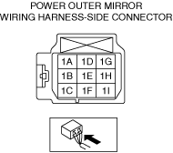
INSPECT POWER OUTER MIRROR FOR MALFUNCTION
• Inspect the applicable part.
• Is the part normal?
|
Yes
|
Go to the next step.
|
|
No
|
Repair or replace the malfunctioning location and perform the repair completion verification.
|
|
6
|
INSPECT ACTIVE DRIVING DISPLAY FOR MALFUNCTION
• Inspect the applicable part.
• Is the part normal?
|
Yes
|
Go to the next step.
|
|
No
|
Repair or replace the malfunctioning location and perform the repair completion verification.
|
|
7
|
INSPECT INSTRUMENT CLUSTER FOR MALFUNCTION
• Inspect the applicable part.
• Is the part normal?
|
Yes
|
Go to the next step.
|
|
No
|
Repair or replace the malfunctioning location and perform the repair completion verification.
|
|
Repair completion verification
|
VERIFY THAT VEHICLE IS REPAIRED
• Install/connect the part removed/disconnected during the troubleshooting procedure.
• Has the malfunction symptom been eliminated?
|
Yes
|
Complete the symptom troubleshooting. (Explain contents of repair to customer)
|
|
No
|
Refer to the controller area network (CAN) malfunction diagnosis flow to inspect for a CAN communication error.
If the CAN communication is normal, perform the diagnosis from Step 1.
• If the malfunction is not resolved, replace the rear side radar sensor.
|