DTC P1A1C:00 [MZR 2.0 DISI i-stop]


id0102d4950000

DTC P1A1C:00

Power relay and/or power drive relay performance problem

DETECTION CONDITION
•  The PCM calculates the number of times the power relay and power drive relay operation and records the value in the built-in non-volatile ROM. The PCM records DTCs when the number of times the power relay and power drive relay has been operated reaches the warrantied performance frequency for the power relay and power drive relay.
•  Detects DTC if any of the following conditions are met:
―  The average of the electric potential difference between the main battery and the sub-battery is 3 V or more while the power relay/power drive relay is commanded on when the engine is started using the IG key.
―  The charge/discharge flow of the sub-battery exceeds 3 A for a continuous 3 s or more with the charge relay, power relay, and power drive relay in the off condition after starting the engine.
―  The electric potential difference between the main battery and the sub-battery is 0.2 V or less with the charge relay, power relay, and power drive relay in the off condition after starting the engine.
Diagnostic support note
•  This is a continuous monitor (other).
•  The MIL does not illuminate.
•  FREEZE FRAME DATA (Mode 2)/Snapshot data is not available.
•  The DTC is stored in the PCM memory.
POSSIBLE CAUSE
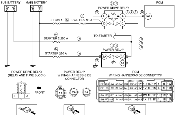
•  Power drive relay malfunction
•  Short to ground in wiring harness between power drive relay terminal A and PCM terminal 1AL
•  Short to ground or open circuit in power drive relay power supply circuit
―  Short to ground in wiring harness between main battery positive terminal and power drive relay terminal E
―  Short to ground in wiring harness between main battery positive terminal and power drive relay terminal D
―  PWR DRV 30 A fuse malfunction
―  Open circuit in wiring harness between main battery positive terminal and power drive relay terminal E
―  Open circuit in wiring harness between main battery positive terminal and power drive relay terminal D
•  PCM connector or terminals malfunction
•  Open circuit in wiring harness between power drive relay terminal A and PCM terminal 1AL
•  Short to power supply in wiring harness between power drive relay terminal A and PCM terminal 1AL
•  Open circuit in power relay ground
•  Power relay malfunction
•  Short to ground in wiring harness between power drive relay terminal C and power relay terminal 1A
•  Short to power supply in wiring harness between power drive relay terminal C and power relay terminal 1A
•  Open circuit in wiring harness between power drive relay terminal C and power relay terminal 1A
•  Short to ground or open circuit in power relay circuit
―  Short to ground in wiring harness between main battery positive terminal and power relay terminal 3A
―  Short to ground in wiring harness between sub battery positive terminal and power relay terminal 2A
―  STARTER 250 A fuse malfunction
―  STARTER 2 250 A fuse malfunction
―  Open circuit in wiring harness between main battery positive terminal and power relay terminal 3A
―  Open circuit in wiring harness between sub battery positive terminal and power relay terminal 2A
•  Number of times power relay and power drive relay has been operated has reached warrantied performance frequency for power relay and power drive relay.
•  PCM malfunction

Diagnostic procedure

STEP

INSPECTION

ACTION

1
VERIFY RELATED SERVICE INFORMATION AVAILABILITY
•  Verify related Service Information availability.
•  Is any related Service Information available?
Yes
Perform repair or diagnosis according to the available Service Information.
•  If the vehicle is not repaired, go to the next step.
No
Go to the next step.
2
VERIFY RELATED PENDING CODE AND/OR DTC
•  Switch the ignition to off, then to ON (engine off).
•  Perform the Pending Trouble Code Access Procedure and DTC Reading Procedure.
•  Is the PENDING CODE/or DTC P0B25:00 or P0B29:00 also present?
Yes
Go to the applicable PENDING CODE or DTC inspection.
No
Go to the next step.
3
INSPECT POWER DRIVE RELAY
•  Switch the ignition to off.
•  Remove the power drive relay.
•  Inspect the power drive relay.
•  Is there any malfunction?
Yes
Go to Step 15.
No
Go to the next step.
4
INSPECT POWER DRIVE RELAY SIGNAL CIRCUIT FOR SHORT TO GROUND
•  Power drive relay is removed.
•  Inspect for continuity between power drive relay terminal A (wiring harness-side) and body ground.
•  Is there continuity?
Yes
If the short to ground circuit could be detected:
•  Repair or replace the wiring harness for a possible short to ground.
If the short to ground circuit could not be detected:
•  Replace the PCM (short to ground in PCM internal circuit).
Go to Step 16.
No
Go to the next step.
5
INSPECT POWER DRIVE RELAY POWER SUPPLY CIRCUIT FOR SHORT TO GROUND OR OPEN CIRCUIT
•  Power drive relay is removed.
•  Measure the voltage at the following terminals (wiring harness-side):
―  Power drive relay terminal E
―  Power drive relay terminal D
•  Is the voltage B+?
Yes
Go to the next step.
No
Inspect the PWR DRV 30 A fuse.
•  If the fuse is melt:
―  Repair or replace the wiring harness for a possible short to ground.
―  Replace the fuse.
•  If the fuse is deterioration:
―  Replace the fuse.
•  If the fuse is normal:
―  Repair or replace the wiring harness for a possible open circuit.
Go to Step 16.
6
INSPECT PCM CONNECTOR CONDITION
•  Disconnect the PCM connector.
•  Inspect for poor connection (such as damaged/pulled-out pins, corrosion).
•  Is there any malfunction?
Yes
Repair or replace the terminal and/or connector, then go to Step 16.
No
Go to the next step.
7
INSPECT POWER DRIVE RELAY SIGNAL CIRCUIT FOR OPEN CIRCUIT
•  Power drive relay is removed.
•  PCM connector is disconnected.
•  Inspect for continuity between power drive relay terminal A (wiring harness-side) and PCM terminal 1AL (wiring harness-side).
•  Is there continuity?
Yes
Go to the next step.
No
Repair or replace the wiring harness for a possible open circuit, then go to Step 16.
8
INSPECT POWER DRIVE RELAY SIGNAL CIRCUIT FOR SHORT TO POWER SUPPLY
•  Power drive relay is removed.
•  PCM connector is disconnected.
•  Switch the ignition to ON (engine off).
•  Measure the voltage at the power drive relay terminal A (wiring harness-side).
•  Is there any voltage?
Yes
Repair or replace the wiring harness for a possible short to power supply, then go to Step 16.
No
Go to the next step.
9
INSPECT POWER RELAY GROUND FOR OPEN CIRCUIT
•  Switch the ignition to off.
•  Inspect the installation of power relay.
•  Is the power relay installed securely?
Yes
Go to the next step.
No
Retighten the power relay, then go to Step 16.
10
INSPECT POWER RELAY
•  Remove the power relay.
•  Inspect the power relay.
•  Is there any malfunction?
Yes
Go to Step 15.
No
Go to the next step.
11
INSPECT POWER RELAY POWER SUPPLY CIRCUIT FOR SHORT TO GROUND
•  Power drive relay and power relay are removed.
•  PCM connector is disconnected.
•  Inspect for continuity between power relay terminal 1A (wiring harness-side) and body ground.
•  Is there continuity?
Yes
Repair or replace the wiring harness for a possible short to ground, then go to Step 16.
No
Go to the next step.
12
INSPECT POWER RELAY POWER SUPPLY CIRCUIT FOR SHORT TO POWER SUPPLY
•  Power drive relay and power relay are removed.
•  PCM connector is disconnected.
•  Switch the ignition to ON (engine off).
•  Measure the voltage at the power relay terminal 1A (wiring harness-side).
•  Is there any voltage?
Yes
Repair or replace the wiring harness for a possible short to power supply, then go to Step 16.
No
Go to the next step.
13
INSPECT POWER RELAY POWER SUPPLY CIRCUIT FOR OPEN CIRCUIT
•  Power drive relay and power relay are removed.
•  PCM connector is disconnected.
•  Switch the ignition to off.
•  Inspect for continuity between power drive relay terminal C (wiring harness-side) and power relay terminal 1A (wiring harness-side).
•  Is there continuity?
Yes
Go to the next step.
No
Repair or replace the wiring harness for a possible open circuit, then go to Step 16.
14
INSPECT POWER RELAY CIRCUIT FOR SHORT TO GROUND OR OPEN CIRCUIT
•  Power drive relay and power relay are removed.
•  PCM connector is disconnected.
•  Measure the voltage at the following terminals (wiring harness-side):
―  Power relay terminal 2A
―  Power relay terminal 3A
•  Is the voltage B+?
Yes
Go to the next step.
No
Inspect the STARTER 250 A fuse and STARTER 2 250 A fuse.
•  If the fuse is melt:
―  Repair or replace the wiring harness for a possible short to ground.
―  Replace the malfunctioning fuse.
•  If the fuse is deterioration:
―  Replace the malfunctioning fuse.
•  If the fuse is normal:
―  Repair or replace the wiring harness for a possible open circuit.
Go to the next step.
15
REPLACE POWER DRIVE RELAY AND POWER RELAY
•  Replace the power drive relay and power relay.
•  Reset the operational frequency of the power drive relay and power relay using the M-MDS.
Go to the next step.
16
VERIFY DTC TROUBLESHOOTING COMPLETED
•  Make sure to reconnect all disconnected connectors.
•  Clear the DTC from the PCM memory using the M-MDS.
•  Perform the KOEO or KOER self test.
•  Is the same DTC present?
Yes
Repeat the inspection from Step 1.
•  If the malfunction recurs, replace the PCM.
Go to the next step.
No
Go to the next step.
17
VERIFY AFTER REPAIR PROCEDURE
•  Perform the “AFTER REPAIR PROCEDURE”.
•  Are any DTCs present?
Yes
Go to the applicable DTC inspection.
No
DTC troubleshooting completed.