|
1
|
VERIFY RELATED SERVICE INFORMATION AVAILABILITY
• Verify related Service Information availability.
• Is any related Service Information available?
|
Yes
|
Perform repair or diagnosis according to the available Service Information.
• If the vehicle is not repaired, go to the next step.
|
|
No
|
Go to the next step.
|
|
2
|
VERIFY THAT THE i-stop WARNING LIGHT (AMBER) flashes
• Does the i-stop warning light (amber) flash?
|
Yes
|
Replace the sub battery.
Go to the next step.
|
|
No
|
Go to Step 5.
|
|
3
|
INSPECT THE ELECTROLYTE GRAVITY OF THE MAIN BATTERY
• Inspect the electrolyte specific gravity of the main battery.
• Is the electrolyte gravity of all the cells within the 1.17—1.22 range?
|
Yes
|
Recharge the main battery.
Go to the next step.
|
|
No
|
When the electrolyte gravity is 1.16 or less
• Replace the main battery
• Go to the next step.
When the electrolyte gravity is 1.22 or more
• Go to Step 8.
|
|
4
|
ONCE AGAIN INSPECT THE ELECTROLYTE GRAVITY OF THE MAIN BATTERY
• Once again inspect the electrolyte gravity of the main battery.
• Is the electrolyte gravity of all the cells 1.21 or more?
|
Yes
|
Go to Step 8.
|
|
No
|
Replace the main battery.
Go to Step 8.
|
|
5
|
INSPECT SUB BATTERY
• Inspect the sub battery.
• Is there any malfunction?
|
Yes
|
Recharge or replace the sub battery, then go to Step 8.
|
|
No
|
Go to the next step.
|
|
6
|
INSPECT PCM CONNECTOR CONDITION
• Switch the ignition to off.
• Disconnect the PCM connector.
• Inspect for poor connection (such as damaged/pulled-out pins, and corrosion).
• Is there any malfunction?
|
Yes
|
Repair or replace the terminal and/or connector, then go to Step 8.
|
|
No
|
Go to the next step.
|
|
7
|
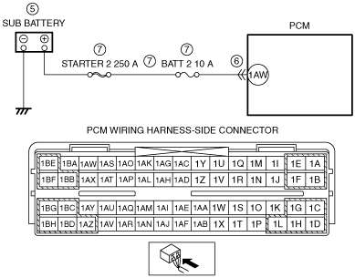
INSPECT SUB BATTERY CIRCUIT FOR SHORT TO GROUND OR OPEN CIRCUIT
• PCM connectors is disconnected.
• Measure the voltage at the PCM terminal 1AW (wiring harness-side).
• Is the voltage B+?
|
Yes
|
Go to the next step.
|
|
No
|
Inspect the STARTER 2 250 A fuse and BATT 2 10 A fuse.
• If the fuse is melt:
-
― Repair or replace the wiring harness for a possible short to ground.
― Replace the malfunctioning fuse.
• If the fuse is deterioration:
-
― Replace the malfunctioning fuse.
• If the fuse is normal:
-
― Repair or replace the wiring harness for a possible open circuit.
Go to Step 8.
|
|
8
|
VERIFY DTC TROUBLESHOOTING COMPLETED
• Make sure to reconnect all disconnected connectors.
• Clear the DTC from the PCM memory using the M-MDS.
• Perform the KOEO or KOER self test.
• Is the same DTC present?
|
Yes
|
Repeat the inspection from Step 1.
• If the malfunction recurs, replace the PCM.
Go to the next step.
|
|
No
|
Go to the next step.
|
|
9
|
VERIFY AFTER REPAIR PROCEDURE
• Perform the “AFTER REPAIR PROCEDURE”.
• Are any DTCs present?
|
Yes
|
Go to the applicable DTC inspection.
|
|
No
|
DTC troubleshooting completed.
|