ON-BOARD DIAGNOSTIC TEST [MZ-CD 1.6 (Y6) (EURO4 emission level)]
id0102g6801000
DTCs Retrieving Procedure
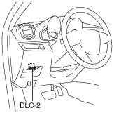
1. Connect the M-MDS to the DLC-2.
2. After the vehicle is identified, select the following items from the initial screen of the M-MDS.
-
• When using the IDS (notebook PC)
-
1. Select the “Toolbox” tab.
2. Select “Self Test”.
3. Select “Modules”.
4. Select “PCM”.
-
• When using the PDS (pocket PC)
-
1. Select “Module Tests”.
2. Select “PCM”.
3. Select “Self Test”.
3. Then, select the “Retrieve CMDTCs” and perform procedures according to directions on the M-MDS screen.
4. Verify the DTC according to the directions on the M-MDS screen.
-
• If any DTCs are displayed, perform troubleshooting according to the corresponding DTC inspection.
5. After completion of repairs, clear all DTCs stored in the PCM, while referring to “AFTER REPAIR PROCEDURE“.
DTC Reading Procedure
1. Connect the M-MDS to the DLC-2.
2. After the vehicle is identified, select the following items from the initial screen of the M-MDS.
-
• When using the IDS (notebook PC)
-
1. Select the “Toolbox” tab.
2. Select “Self Test”.
3. Select “Modules”.
4. Select “PCM”.
-
• When using the PDS (pocket PC)
-
1. Select “Module Tests”.
2. Select “PCM”.
3. Select “Self Test”.
3. Then, select the “Retrieve CMDTCs” and perform procedures according to directions on the M-MDS screen.
4. Verify the DTC according to the directions on the M-MDS screen.
-
• If any DTCs are displayed, perform troubleshooting according to the corresponding DTC inspection.
5. After completion of repairs, clear all DTCs stored in the PCM, while referring to “AFTER REPAIR PROCEDURE“.
Pending Trouble Code Access Procedure
1. Connect the M-MDS to the DLC-2.
2. After the vehicle is identified, select the following items from the initial screen of the M-MDS.
-
• When using the IDS (notebook PC)
-
1. Select the “Toolbox” tab.
2. Select “Self Test”.
3. Select “Modules”.
4. Select “PCM”.
-
• When using the PDS (pocket PC)
-
1. Select “Module Tests”.
2. Select “PCM”.
3. Select “Self Test”.
3. Then, select the “Retrieve CMDTCs” and perform procedures according to directions on the M-MDS screen.
4. Retrieve the pending trouble codes according to the directions on the M-MDS screen.
Freeze Frame PID Data Access Procedure
1. Connect the M-MDS to the DLC-2.
2. After the vehicle is identified, select the following items from the initial screen of the M-MDS.
-
• When using the IDS (notebook PC)
-
1. Select the “Toolbox” tab.
2. Select “Self Test”.
3. Select “Modules”.
4. Select “PCM”.
-
• When using the PDS (pocket PC)
-
1. Select “Module Tests”.
2. Select “PCM”.
3. Select “Self Test”.
3. Then, select the “Retrieve CMDTCs” and perform procedures according to directions on the M-MDS screen.
4. Retrieve the freeze frame PID data according to the directions on the M-MDS screen.
-
Note
-
• Freeze frame data appears at the top of the help screen when the displayed DTC is selected.
• The freeze frame data consists of data for vehicle and engine control system operation conditions when malfunctions in the engine control system are detected and stored in the PCM.
• There are modes 2 and 12 in the freeze frame data.
Freeze frame data (mode 2)
• Freeze frame data is stored at the instant the malfunction indicator lamp illuminates, and only a part of the DTC data is stored.
• For the freeze frame data, if there are several malfunctions in the engine control system, the data for the malfunction which occurred initially is stored. Thereafter, if a misfire or fuel injection control malfunction occurs, data from the misfire or fuel injection control malfunction is written over the initially stored data. However, if the initially stored freeze frame data is a misfire or fuel injection control malfunction, it is not overwritten.
Freeze frame data (mode 12)
• The data for DTCs currently detected is stored.
• The DTC recording timing differs depending on the number of DTC drive cycles.
-
― For a DTC with a drive cycle number 1, only the malfunction determination data is recorded.
― For a DTC with a drive cycle number 2, both the malfunction determination and undetermined data is recorded.
Freeze frame data table (mode2, mode12) table
-
Note
-
• Freeze frame data items are not displayed, according to detected DTC.
|
Freeze frame data item
|
Unit
|
Description
|
Corresponding PID data monitor item
|
|
LOAD
|
%
|
Calculated engine load
|
LOAD
|
|
ECT
|
°C
|
Engine coolant temperature
|
ECT
|
|
MAP
|
kPa
|
Manifold absolute pressure
|
MAP
|
|
RPM
|
RPM
|
Engine speed
|
RPM
|
|
VS
|
KPH
|
Vehicle speed
|
VSS
|
|
IAT
|
°C
|
Intake air temperature
|
IAT
|
|
MAF
|
g/sec
|
Mass airflow
|
MAF
|
|
FRP
|
kPa
|
Fuel pressure
|
FRP
|
|
APP_D
|
%
|
Accelerator pedal position No.1
|
APP1
|
On-Board System Readiness Tests Access Procedure
1. Connect the M-MDS to the DLC-2.
2. After the vehicle is identified, select the following items from the initial screen of the M-MDS.
-
• When using the IDS (notebook PC)
-
1. Select the “Toolbox” tab
2. Select “Powertrain”
3. Select “OBD Test Modes”
4. Select “Mode 1 Powertrain Data”
-
• When using the PDS (pocket PC)
-
1. Select “OBDII Modes”
2. Select “Mode 1 Powertrain Data”
3. Select “PCM”
3. Then, select the "***SUP" and "***EVAL" PIDs in the PID selection screen.
4. Monitor those PIDs and check it system monitor is completed.
PID/DATA Monitor and Record Procedure
-
Note
-
• The PID/DATA MONITOR function monitors the calculated value of the input/output signals in the PCM. Therefore, an output device malfunction is not directly indicated as a malfunction of the monitored value for the output device. If a monitored value of an output device is out of specification, inspect the monitored value of the input device related to the output control.
1. Connect the M-MDS to the DLC-2.
2. After the vehicle is identified, select the following items from the initial screen of the M-MDS.
-
• When using the IDS (notebook PC)
-
1. Select the “Toolbox” tab.
2. Select “DataLogger”.
3. Select “Modules”.
4. Select “PCM”.
-
• When using the PDS (pocket PC)
-
1. Select “Module Tests”.
2. Select “PCM”.
3. Select “DataLogger”.
3. Select the PID from the PID table.
4. Verify the PID data according to the directions on the screen.
Active Command Mode Function Procedure
1. Connect the M-MDS to the DLC-2.
2. After the vehicle is identified, select the following items from the initial screen of the M-MDS.
-
• When using the IDS (notebook PC)
-
1. Select the “Toolbox” tab.
2. Select “DataLogger”.
3. Select “Modules”.
4. Select “PCM”.
-
• When using the PDS (pocket PC)
-
1. Select “Module Tests”.
2. Select “PCM”.
3. Select “DataLogger”.
3. Select the simulation items from the PID table.
4. Perform the simulation function, inspect the operations for each parts.
-
• If there is no operation sound from the relay, motor, and solenoid after the simulation function inspection is performed, it is possible that there is an open or short circuit in the wiring harness, relay, motor or solenoid, or sticking and operation malfunction.