DTC P0488 [MZ-CD 1.6 (Y6) (EURO4 emission level)]


id0102g6832300

DTC P0488

EGR throttle valve control circuit range/performance

DETECTION CONDITION
•  If the PCM detects any of the following conditions, the PCM determines that there is a malfunction in the EGR throttle valve control circuit.
―  The PCM learns the EGR throttle valve position based on the EGR throttle valve position sensor signal. The learning value for the EGR throttle valve position is any of the following:
•  Difference between the initial value of the EGR throttle valve position exceeds 55 %
•  Difference between the latest EGR throttle valve position exceeds 13 %
―  The PCM monitors the EGR throttle valve actuator control signal circuit at PCM terminal 247. If the PCM detects that EGR throttle valve actuator control circuit is no load for 2s when the PCM duty-controls the air bypass valve actuator.
―  The PCM monitors the EGR throttle valve actuator control signal circuit at PCM terminal 247. The temperature of the power stage module for the EGR throttle bypass valve actuator in the PCM is detected as excessively high for 2 s while the PCM is performing duty control on the EGR throttle valve actuator
―  The PCM monitors the EGR throttle valve position based on the signal from the EGR throttle valve position sensor and compares the target value with it. The following condition is detected:
•  Difference between the target value and actual value for the EGR throttle valve exceeds threshold for 5 s
POSSIBLE CAUSE
•  EGR throttle valve base value reset procedure improperly
•  EGR throttle valve connector or terminal malfunction
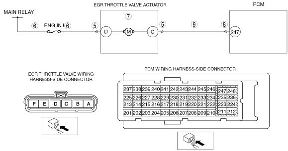
•  Open circuit in wiring harness between main relay terminal D and EGR throttle valve terminal D
•  Short to ground in wiring harness between ENG INJ fuse and EGR throttle valve terminal D
•  EGR throttle valve stuck
•  Contaminate in EGR throttle valve
•  PCM connector or terminal malfunction
•  Open circuit in wiring harness between EGR throttle valve terminal C and PCM terminal 247
•  EGR throttle valve position sensor malfunction
•  EGR throttle valve actuator malfunction
•  PCM malfunction

Diagnostic procedure

STEP

INSPECTION

ACTION

1
VERIFY FREEZE FRAME DATA HAS BEEN RECORDED
•  Has the FREEZE FRAME DATA been recorded?
Yes
Go to the next step.
No
Record the FREEZE FRAME DATA on the repair order, then go to the next step.
2
VERIFY RELATED REPAIR INFORMATION AVAILABILITY
•  Verify related service repair information availability.
•  Is any related repair information available?
Yes
Perform repair or diagnosis according to the available repair information.
•  If the vehicle is not repaired, go to the next step.
No
Go to the next step.
3
VERIFY RELATED PENDING CODE AND/OR DTC
•  Switch the ignition to off, then to ON (engine off).
•  Perform the Pending Trouble Code Access Procedure and DTC Reading Procedure.
•  Is the following PENDING CODE/DTC also present?
―  P0407, P0408, P2141, P2142
Yes
Go to the applicable DTC inspection.
No
Go to the next step.
4
PERFORM EGR THROTTLE VALVE BASE VALUE RESET
•  Clear the DTC from the PCM memory using the M-MDS.
•  Perform the EGR THROTTLE VALVE BASE VALUE RESET procedures.
•  Run the vehicle under the FREEZE FRAME DATA stored condition.
•  Is the same DTC present?
Yes
Go to the next step.
No
Troubleshooting is completed.
Go to Step 10.
5
INSPECT EGR THROTTLE VALVE CONNECTOR CONDITION
•  Switch the ignition to OFF.
•  Disconnect the air bypass valve connector.
•  Inspect for poor connection (such as damaged/pulled-out pins, corrosion).
•  Is there any malfunction?
Yes
Repair or replace the connector and/or terminals, then go to Step 10.
No
Go to the next step.
6
INSPECT EGR THROTTLE VALVE ACTUATOR POWER SUPPLY CIRCUIT FOR OPEN OR SHORT TO GROUND
•  Air bypass valve connector is disconnected.
•  Switch the ignition to ON (engine off).
•  Measure the voltage at the EGR throttle valve terminal D (wiring harness-side).
•  Is the voltage B+?
Yes
Go to the next step.
No
Verify the ENG INJ fuse condition.
•  If the ENG INJ fuse is blown, repair or replace wiring harness for a possible short to ground circuit.
•  If the ENG INJ fuse is normal, repair or replace wiring harness for a possible open circuit.
Then go to Step 10.
7
VISUALLY INSPECT EGR THROTTLE VALVE FOR CONTAMINATION
•  Remove the EGR throttle valve component.
•  Is there any contamination?
Yes
Clean the EGR throttle valve, then go to Step 10.
No
Go to the next step.
8
INSPECT PCM CONNECTOR CONDITION
•  Disconnect the PCM connector.
•  Inspect for poor connection (such as damaged/pulled-out pins, corrosion).
•  Is there any malfunction?
Yes
Repair or replace the connector and/or terminals, then go to Step 10.
No
Go to the next step.
9
INSPECT EGR THROTTLE VALVE ACTUATOR CONTROL CIRCUIT FOR OPEN
•  EGR throttle valve and PCM connectors are disconnected.
•  Inspect continuity between EGR throttle valve C (wiring harness-side) and PCM terminal 247 (wiring harness-side).
•  Is there continuity?
Yes
Replace the EGR throttle valve component, then go to the next step.
No
Repair or replace the wiring harness for a possible open circuit, then go to the next step.
10
VERIFY THAT DTC P0488 TROUBLESHOOTING IS COMPLETED
•  Make sure to reconnect all disconnected connectors.
•  Clear the DTC from the PCM memory using the M-MDS.
•  Run the vehicle under the FREEZE FRAME DATA stored condition.
•  Is the same DTC present?
Yes
Repeat the inspection from Step 1.
•  If the malfunction recurs, replace the PCM.
Go to the next step.
No
Go to the next step.
11
VERIFY AFTER REPAIR PROCEDURE
•  Perform the after repair procedure.
•  Are any DTCs present?
Yes
Go to the applicable DTC inspection.
No
DTC troubleshooting completed.