DTC P1295 [MZ-CD 1.6 (Y6) (EURO4 emission level)]
id0102g6836600
DTC P1295 |
Fuel injector multiple faults |
---|---|
DETECTION CONDITION
|
• The PCM monitors the voltage of the fuel injector control circuit. While the PCM is performing the fuel injector control, if voltage does not change at multiple fuel injector control circuits, the PCM determines that there are multiple malfunctions in the fuel injector control circuits.
|
POSSIBLE CAUSE
|
• Fuel injector connector or terminal malfunction
• PCM connector or terminal malfunction
• Fuel injector control circuits high and low are short to each other
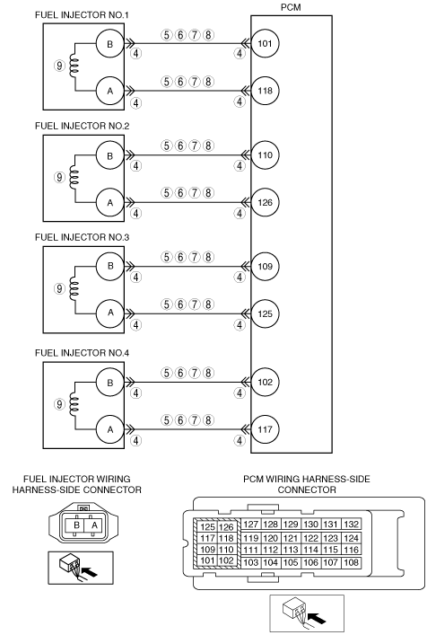
• Short to ground in the wiring harness between fuel injector No.1 terminal A and PCM terminal 118
• Short to ground in the wiring harness between fuel injector No.2 terminal A and PCM terminal 126
• Short to ground in the wiring harness between fuel injector No.3 terminal A and PCM terminal 125
• Short to ground in the wiring harness between fuel injector No.4 terminal A and PCM terminal 117
• Short to ground in the wiring harness between fuel injector No.1 terminal B and PCM terminal 101
• Short to ground in the wiring harness between fuel injector No.2 terminal B and PCM terminal 110
• Short to ground in the wiring harness between fuel injector No.3 terminal B and PCM terminal 109
• Short to ground in the wiring harness between fuel injector No.4 terminal B and PCM terminal 102
• Short to power supply in the wiring harness between fuel injector No.1 terminal A and PCM terminal 118
• Short to power supply in the wiring harness between fuel injector No.2 terminal A and PCM terminal 126
• Short to power supply in the wiring harness between fuel injector No.3 terminal A and PCM terminal 125
• Short to power supply in the wiring harness between fuel injector No.4 terminal A and PCM terminal 117
• Short to power supply in the wiring harness between fuel injector No.1 terminal B and PCM terminal 101
• Short to power supply in the wiring harness between fuel injector No.2 terminal B and PCM terminal 110
• Short to power supply in the wiring harness between fuel injector No.3 terminal B and PCM terminal 109
• Short to power supply in the wiring harness between fuel injector No.4 terminal B and PCM terminal 102
• Open circuit in the wiring harness between fuel injector No.1 terminal A and PCM terminal 118
• Open circuit in the wiring harness between fuel injector No.1 terminal B and PCM terminal 101
• Open circuit in the wiring harness between fuel injector No.2 terminal A and PCM terminal 126
• Open circuit in the wiring harness between fuel injector No.2 terminal B and PCM terminal 110
• Open circuit in the wiring harness between fuel injector No.3 terminal A and PCM terminal 125
• Open circuit in the wiring harness between fuel injector No.3 terminal B and PCM terminal 109
• Open circuit in the wiring harness between fuel injector No.4 terminal A and PCM terminal 117
• Open circuit in the wiring harness between fuel injector No.4 terminal B and PCM terminal 102
• Fuel injector No.1 malfunction
• Fuel injector No.2 malfunction
• Fuel injector No.3 malfunction
• Fuel injector No.4 malfunction
• PCM malfunction
|
![]() |
Diagnostic procedure
STEP |
INSPECTION |
ACTION |
|
---|---|---|---|
1
|
VERIFY FREEZE FRAME DATA HAS BEEN RECORDED
• Has the FREEZE FRAME DATA been recorded?
|
Yes
|
Go to the next step.
|
No
|
Record the FREEZE FRAME DATA on the repair order, then go to the next step.
|
||
2
|
VERIFY RELATED REPAIR INFORMATION AVAILABILITY
• Verify related service repair information availability.
• Is any related repair information available?
|
Yes
|
Perform repair or diagnosis according to the available repair information.
• If the vehicle is not repaired, go to the next step.
|
No
|
Go to the next step.
|
||
3
|
VERIFY RELATED PENDING CODE AND/OR DTC
• Switch the ignition to off, then to ON (engine off).
• Perform the Pending Trouble Code Access Procedure and DTC Reading Procedure.
• Is the following PENDING CODE/DTC also present?
|
Yes
|
Go to the applicable DTC inspection.
|
No
|
Go to the next step.
|
||
4
|
INSPECT PCM AND FUEL INJECTOR CONNECTOR CONDITION
• Switch the ignition to off.
• Disconnect the PCM and all fuel injector connectors.
• Inspect for poor connection (such as damaged/pulled-out pins, corrosion).
• Is there any malfunction?
|
Yes
|
Repair or replace the connector and/or terminals, then go to Step 10.
|
No
|
Go to the next step.
|
||
5
|
INSPECT FUEL INJECTOR HIGH-SIDE CIRCUIT AND LOW-SIDE CIRCUIT FOR SHORT TO EACH OTHER
• All fuel injector and PCM connectors are disconnected.
• Inspect for continuity between each fuel injector terminals A and B (wiring harness-side).
• Is there continuity?
|
Yes
|
Repair or replace the wiring harness for a possible short to each other, then go to Step 10.
|
No
|
Go to the next step.
|
||
6
|
INSPECT FUEL INJECTOR CIRCUITS FOR SHORT TO GROUND
• All fuel injector and PCM connectors are disconnected.
• Inspect for continuity between the following terminals (wiring harness-side) and body ground:
• Is there continuity?
|
Yes
|
Repair or replace the wiring harness for a possible short to ground, then go to Step 10.
|
No
|
Go to the next step.
|
||
7
|
INSPECT FUEL INJECTOR CIRCUITS FOR SHORT TO POWER SUPPLY
• All fuel injector and PCM connectors are disconnected.
• Switch the ignition to ON (Engine off).
• Measure the voltage between the following terminals (wiring harness-side) and body ground:
• Is the voltage B+?
|
Yes
|
Repair or replace the wiring harness for a possible short to power supply, then go to Step 10.
|
No
|
Go to the next step.
|
||
8
|
INSPECT FUEL INJECTOR CIRCUITS FOR OPEN CIRCUIT
• Switch the ignition to OFF.
• Fuel injector No.1 and PCM connectors are disconnected.
• Inspect for continuity between the following terminals (wiring harness-side):
• Is there continuity?
|
Yes
|
Go to the next step.
|
No
|
Repair or replace the wiring harness for a possible open circuit, then go to Step 10.
|
||
9
|
INSPECT FUEL INJECTOR
• Inspect the fuel injector for all cylinders.
• Is there any malfunction?
|
Yes
|
Replace the suspect fuel injector, then go to the next step.
|
No
|
Go to the next step.
|
||
10
|
VERIFY THAT DTC P1295 TROUBLESHOOTING IS COMPLETED
• Make sure to reconnect all disconnected connectors.
• Clear the DTC from the PCM memory using the M-MDS.
• Run the vehicle under the FREEZE FRAME DATA stored condition.
• Is the same DTC present?
|
Yes
|
Repeat the inspection from Step 1.
• If the malfunction recurs, replace the PCM.
Go to the next step.
|
No
|
Go to the next step.
|
||
11
|
VERIFY AFTER REPAIR PROCEDURE
• Perform the after repair procedure.
• Are any DTCs present?
|
Yes
|
Go to the applicable DTC inspection.
|
No
|
DTC troubleshooting completed.
|