DTC P062B [MZ-CD 1.6 (Y6) (EURO4 emission level)]


id0102g6877400

DTC P062B

Internal control module - fuel injection control performance

DETECTION CONDITION
•  The PCM monitors the condition of the fuel injector drive circuit. When the fuel injector drive signal is off during PCM initialization after it is activated. If any of the following conditions is met, the PCM determines that there is a malfunction in the fuel injector drive circuit.
―  Fuel injector drive signal does not correspond to function computer and monitoring module during PCM initialization after activating PCM
―  Fuel injector drive signal voltage is low
―  Fuel injector drive signal voltage is high
POSSIBLE CAUSE
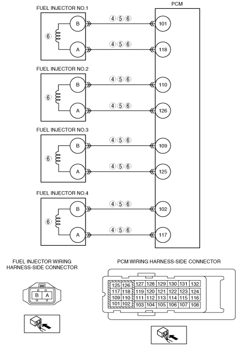
•  Fuel injector control signal high and low circuits are short to each other
•  Short to ground in wiring harness between fuel injector No.1 terminal A and PCM terminal 118
•  Short to ground in wiring harness between fuel injector No.1 terminal B and PCM terminal 101
•  Short to ground in wiring harness between fuel injector No.2 terminal A and PCM terminal 126
•  Short to ground in wiring harness between fuel injector No.2 terminal B and PCM terminal 110
•  Short to ground in wiring harness between fuel injector No.3 terminal A and PCM terminal 125
•  Short to ground in wiring harness between fuel injector No.3 terminal B and PCM terminal 109
•  Short to ground in wiring harness between fuel injector No.4 terminal A and PCM terminal 117
•  Short to ground in wiring harness between fuel injector No.4 terminal B and PCM terminal 102
•  Short to power supply in wiring harness between fuel injector No.1 terminal A and PCM terminal 118
•  Short to power supply in wiring harness between fuel injector No.1 terminal B and PCM terminal 101
•  Short to power supply in wiring harness between fuel injector No.2 terminal A and PCM terminal 126
•  Short to power supply in wiring harness between fuel injector No.2 terminal B and PCM terminal 110
•  Short to power supply in wiring harness between fuel injector No.3 terminal A and PCM terminal 125
•  Short to power supply in wiring harness between fuel injector No.3 terminal B and PCM terminal 109
•  Short to power supply in wiring harness between fuel injector No.4 terminal A and PCM terminal 117
•  Short to power supply in wiring harness between fuel injector No.4 terminal B and PCM terminal 102
•  Fuel injector malfunction
•  PCM internal malfunction.

Diagnostic procedure

STEP

INSPECTION

ACTION

1
VERIFY FREEZE FRAME DATA HAS BEEN RECORDED
•  Has the FREEZE FRAME DATA been recorded?
Yes
Go to the next step.
No
Record the FREEZE FRAME DATA on the repair order, then go to the next step.
2
VERIFY RELATED REPAIR INFORMATION AVAILABILITY
•  Verify related service repair information availability.
•  Is any related repair information available?
Yes
Perform repair or diagnosis according to the available repair information.
•  If the vehicle is not repaired, go to the next step.
No
Go to the next step.
3
VERIFY RELATED PENDING CODE AND/OR DTC
•  Switch the ignition to off, then to ON (engine off).
•  Perform the Pending Trouble Code Access Procedure and DTC Reading Procedure.
•  Is the following PENDING CODE/DTC also present?
―  P1201, P1202, P1203, P1204
Yes
Go to the applicable DTC inspection.
No
Go to the next step.
4
INSPECT FUEL INJECTOR CONTROL SIGNAL HIGH AND LOW CIRCUITS FOR SHORT TO EACH OTHER
•  Switch the ignition to OFF.
•  Disconnect the PCM and fuel injector connectors.
•  Inspect for continuity between the each fuel injector terminal A and B (wiring harness-side)
•  Is there continuity?
Yes
Repair or replace the wiring harness for a possible short to each other, then go Step 7.
No
Go to the next step.
5
INSPECT FUEL INJECTOR CIRCUIT FOR SHORT TO GROUND CIRCUIT
•  Fuel injector and PCM connectors are disconnected.
•  Inspect for continuity between each fuel injector terminals (wiring harness-side) and body ground.
•  Is there continuity?
Yes
Repair or replace the wiring harness for a possible short to ground circuit, then go to Step 7.
No
Go to the next step.
6
INSPECT FUEL INJECTORS CIRCUITS FOR SHORT POWER SUPPLY CIRCUIT
•  Disconnect the PCM and all fuel injector connectors.
•  Switch the ignition to ON (Engine off).
•  Measure the voltage between following fuel injector terminals and body ground.
―  Fuel injector No.1 terminal A
―  Fuel injector No.1 terminal B
―  Fuel injector No.2 terminal A
―  Fuel injector No.2 terminal B
―  Fuel injector No.3 terminal A
―  Fuel injector No.3 terminal B
―  Fuel injector No.4 terminal A
―  Fuel injector No.4 terminal B
•  Is the voltage B+?
Yes
Repair wiring harness for a possible short to power supply circuit, then go to the next step.
No
Replace the fuel injector, then go to the next step.
7
VERIFY THAT DTC P062B TROUBLESHOOTING IS COMPLETED
•  Make sure to reconnect all disconnected connectors.
•  Clear the DTC from the PCM memory using the M-MDS.
•  Run the vehicle under the FREEZE FRAME DATA stored condition.
•  Is the same DTC present?
Yes
Repeat the inspection from Step 1.
•  If the malfunction recurs, replace the PCM.
Go to the next step.
No
Go to the next step.
8
VERIFY AFTER REPAIR PROCEDURE
•  Perform the after repair procedure.
•  Are any DTCs present?
Yes
Go to the applicable DTC inspection.
No
DTC troubleshooting completed.