|
am3zzw00005228
PCM REMOVAL/INSTALLATION [LF, L5]
id0140i8802400
1. When replacing the PCM, perform the following:
2. Remove the battery cover. (See BATTERY REMOVAL/INSTALLATION [LF, L5].)
3. Disconnect the negative battery cable.
4. Remove the battery tray and PCM component. (See BATTERY REMOVAL/INSTALLATION [LF, L5].)
5. Remove the junction memder. (MTX)
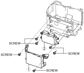
6. Remove in the order indicated in the table.
U.K specs.
am3zzw00005228
|
|
1
|
PCM cover No.2
|
|
2
|
PCM
|
|
3
|
PCM bracket
|
Except for U.k. specs.
am3uuw00002376
|
|
1
|
PCM cover No.2
|
|
2
|
PCM
|
7. Install in the reverse order of removal.
acxaaw00000768
|
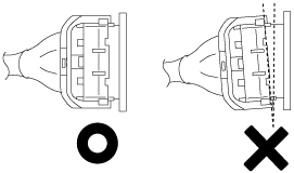
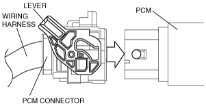
8. Verify that the PCM connector lever is tilted towards the wiring harness side as shown in the figure.
acxaaw00000766
|
9. Insert the PCM connector straight until it contacts the PCM and verify that the lever reverts upward naturally.
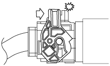
10. Push the lever until a click is heard.
acxaaw00000767
|
11. When replacing the PCM on the vehicles, perform the following: