 |
am3zzn00002803
i-stop CONTROL OPERATION [MZR 2.0 DISI i-stop]
id0140j1778900
Engine stop control
Engine stop control permit conditions (MTX)
|
PURPOSE |
CONDITION ITEM |
|
|---|---|---|
|
Driveability
|
Vehicle speed
|
3 km/h {2 mph} or less
|
|
Accelerator pedal opening angle
|
Fully closed
|
|
|
Clutch pedal opening angle
|
30% or less
|
|
|
Gear position
|
Neutral
|
|
|
Marketability
|
Cabin temperature
|
Climate control unit command
|
|
A/C temperature
|
Climate control unit command
|
|
|
Ambient temperature
|
-10—50 °C {14—122 °F}
|
|
|
Steering wheel operation speed
|
30 °/s or less
(EHPAS after learning center value)
|
|
|
i-stop OFF switch
|
OFF
|
|
|
Vehicle speed record
|
4 km/h {2.4 mph} or more
|
|
|
Advanced key
|
Must be verifiable
(The i-stop operation is also inhibited if the battery for the advanced key is depleted.)
|
|
|
Safety
|
Battery charge status
|
After engine start, full charge determined/not in charge recovery.
|
|
Battery fluid temperature
|
0—70 °C {32—158 °F}
|
|
|
Defroster switch
|
OFF
|
|
|
Front/rear window thermal filaments
|
OFF
|
|
|
Power brake unit vacuum
|
-47 kPa {-353 mmHg, -14 inHg} or less
|
|
|
Door switch
|
OFF
|
|
|
Hood switch
|
ON
|
|
|
Seat belt
|
Fastened
|
|
|
System status
|
i-stop related module normal
|
|
|
System restrictions
|
Engine speed (during engine-stop control)
|
750 rpm
|
|
Number of times starter is operated
|
Within 180,000 times
|
|
|
Number of times starter relay operated
|
Within 180,000 times
|
|
|
Time until engine-stop by i-stop control from vehicle stop
|
0.5 s or more
|
|
|
Engine status
|
Engine coolant temperature
|
55—110 °C {131—230 °F}
|
|
Intake air temperature
|
100 °C {212 °F} or less
|
|
|
Environment status
|
Elevation
|
1,800 m {5906 ft} (+300 m {984 ft}) or less
|
Engine stop control permit conditions (ATX)
|
PURPOSE |
CONDITION ITEM |
|
|---|---|---|
|
Driveability
|
Vehicle speed
|
0 km/h {0 mph}
|
|
Brake switch
|
ON
(if ABS operates during deceleration, i-stop operation is inhibited.)
|
|
|
Brake fluid pressure
|
1.17 MPa {11.9 kgf/cm2, 170 psi} or more
(pedal force sufficient to suppress vehicle lurch when engine is restarted)
|
|
|
Accelerator pedal opening angle
|
Fully closed
|
|
|
Vehicle status
|
Vehicle is stopped in D-range
|
|
|
Marketability
|
Cabin temperature
|
Climate control unit command
|
|
A/C temperature
|
Climate control unit command
|
|
|
Ambient temperature
|
-10—50 °C {14—122 °F}
|
|
|
Steering wheel operation speed
|
10 °/s or less
(EHPAS after learning center value)
|
|
|
Steering angle
|
-65—65 ° (center)
(EHPAS standardizes value after learning center value)
|
|
|
i-stop OFF switch
|
OFF
|
|
|
Vehicle speed record
|
3km/h {2 mph} or more
|
|
|
Advanced key
|
Must be verifiable
(If the auxiliary key is used, the i-stop operation is inhibited. The i-stop operation is also inhibited if the battery for the advanced key is depleted.)
|
|
|
Safety
|
Battery charge status
|
After engine start, full charge determined/not in charge recovery.
|
|
Battery fluid temperature
|
0—70 °C {32—158 °F}
|
|
|
Defroster switch
|
OFF
|
|
|
Front/rear window thermal filaments
|
OFF
|
|
|
Power brake unit vacuum
|
-47 kPa {-353 mmHg, -14 inHg} or less
|
|
|
Door switch
|
OFF
|
|
|
Hood switch
|
ON
|
|
|
Vehicle inclination angle
|
Within + 12% at horizontal
|
|
|
Seat belt
|
Fastened
|
|
|
System status
|
i-stop related module normal
|
|
|
System restrictions
|
Time from engine start
|
8 s or more
|
|
Number of times starter is operated
|
Within 180,000 times
|
|
|
Number of times starter relay operated
|
Within 180,000 times
|
|
|
Time until engine-stop by i-stop control from vehicle stop
|
0.8 s or more
|
|
|
Engine status
|
Engine coolant temperature
|
55—110 °C {131—230 °F}
|
|
Intake air temperature
|
100 °C {212 °F} or less
|
|
|
ATF temperature
|
40—110 °C {104—230 °F}
|
|
|
Environment status
|
Elevation
|
1,500 m {4921 ft} (+300 m {984 ft}) or less
|
Engine-stop control
am3zzn00002803
|
Engine restart control
Engine restart control conditions (MTX)
|
PURPOSE |
CONDITION ITEM |
VECHICLE STATUS |
|
|---|---|---|---|
|
NEUTRAL |
IN GEAR |
||
|
Driver operation
|
Door opened
|
Beeper warning and IS control (engine-stop) continues
|
|
|
Accelerator pedal depressed
|
IS control (engine-stop) continues
|
||
|
Clutch pedal depressed
|
IR
|
||
|
Marketability
|
A/C command
|
IR
|
IS continues
|
|
A/C temperature MAX setting
|
IR
|
IS continues
|
|
|
Battery command (battery charge status)
|
IR
|
IS continues
|
|
|
i-stop OFF switch ON
|
IR
|
IS continues
|
|
|
Advanced key removed after door opened
(Driver seat belt fastened/door closed conditions)
|
IR
|
IS continues
|
|
|
Safety
|
Defroster switch ON
|
IR
|
IS continues
|
|
Front/rear window heater filaments ON
|
IR
|
IS continues
|
|
|
Battery command (battery life)
|
IR
|
IS continues
|
|
|
Power brake unit vacuum: -45 kPa {-338 mmHg, -13 inHg} or more
|
IR
|
IS continues
|
|
|
Vehicle speed: 4 km/h {2.4 mph} or more
|
IR
|
IS continues
|
|
|
Hood opened
|
Engine stall
|
Engine stall
|
|
|
Door opened and seat belt unfastened
|
Engine stall
|
Engine stall
|
|
Engine restart control conditions (ATX)
|
PURPOSE |
CONDITION ITEM |
VECHICLE STATUS |
|
|---|---|---|---|
|
Driver operation
|
Brake pedal is not depressed
|
IR
|
|
|
Accelerator pedal depressed
|
IR
|
||
|
Steering wheel operation speed (D-range):70 °/s or more*1
|
IR
|
||
|
Steering angle (D-range): except -70—70 ° (center)*1
|
IR
|
||
|
Shift operation
|
D-range to M or R position
|
IR
|
|
|
N-range to D or R position
|
IR
|
||
|
R-range to D or R position
|
IR
|
||
|
Marketability
|
A/C command
|
IR
|
|
|
A/C temperature MAX setting
|
IR
|
||
|
Battery command (battery charge status)
|
IR
|
||
|
i-stop OFF switch ON
|
IR
|
||
|
Advanced key removed after door opened
(Driver seat belt fastened/door closed conditions)
|
IR
|
||
|
Safety
|
Defroster switch ON
|
IR
|
|
|
Front/rear window heater filaments ON
|
IR
|
||
|
Brake pedal depression increase
|
IR
|
||
|
Battery command (battery life)
|
IR
|
||
|
Power brake unit vacuum: -45 kPa {-338 mmHg, -13 inHg} or more
|
IR
|
||
|
Vehicle speed: 1 km/h {0.6 mph} or more
|
IR
|
||
|
Electric AT oil pump driver: Drive time 120 s or more
|
IR
|
||
Engine restart control
am3zzn00002804
|
Indicator Light Command (MTX)
|
Classification |
Operation conditions |
Vehicle status |
i-stop indicator/warning display |
Other |
Buzzer |
|||
|---|---|---|---|---|---|---|---|---|
|
Illuminates |
Flashes |
Illuminates |
||||||
|
0.5 s |
0.25 s |
|||||||
|
Directly after vehicle stop
|
IS enable condition from vehicle
|
IS conditions not met
|
IS inhibited (idle)
|
—
|
—
|
—
|
—
|
—
|
|
IS conditions met
|
IS
|
Green
|
—
|
—
|
—
|
—
|
||
|
i-stop
(engine-stop)
|
IS permit status
|
IS continues
|
Green
|
—
|
—
|
—
|
—
|
|
|
IR command via driver operation
|
Clutch pedal depressed (neutral)
|
IR
|
—
|
—
|
—
|
—
|
—
|
|
|
Switch to unsafe status via driver operation
|
In gear
|
IS continues
|
—
|
—
|
Green
|
—
|
—
|
|
|
Door opened
|
IS continues
|
—
|
—
|
Green
|
—
|
0.25 s intervals
|
||
|
Seat belt unfastened and door opened
|
Engine stall
|
Amber *1
|
—
|
Green *1
|
Indicator/warning all illuminated
|
0.25 s intervals
|
||
|
Hood opened
|
Engine stall
|
Amber
|
—
|
—
|
Indicator/warning all illuminated
|
—
|
||
|
IR via vehicle command
|
• Battery command
• Climate control command
• Defroster switch ON
• Front/rear window thermal filaments ON
|
IR
|
—
|
Green *2
|
—
|
—
|
—
|
|
|
• Vehicle moves on road incline
• Power brake unit vacuum reduced
• Battery life
|
IR
|
—
|
—
|
—
|
—
|
—
|
||
|
Advanced key outside of vehicle
|
IR
|
—
|
—
|
—
|
—
|
Keyless control module
Normal buzzer
|
||
|
IR error
|
Engine restart (permitted 3 times)
|
IS continues
|
Green
|
—
|
—
|
—
|
—
|
|
|
IR not possible
|
Engine restart
(failure 3 times)
|
Engine stall
|
Amber
|
—
|
—
|
—
|
—
|
|
|
i-stop OFF switch operation
|
i-stop OFF operation
|
i-stop OFF switch ON (long press, 0.5 s or more)
|
IS not possible
|
Amber
|
—
|
—
|
—
|
Beep
1 time
|
|
i-stop recover operation
|
i-stop OFF switch OFF (long press, 0.5 s or more)
|
IS permitted
|
Amber*3
|
—
|
—
|
—
|
Beep
1 time
|
|
|
Malfunction
|
System malfunction
|
IS not permitted
(idle)
|
—
|
Amber
|
—
|
—
|
—
|
|
Indicator Light Command (ATX)
|
Classification |
Operation conditions |
Vehicle status |
i-stop indicator (Green)/warning display (Amber) |
Indicator (other) |
Buzzer |
|||
|---|---|---|---|---|---|---|---|---|
|
Illuminates |
Flashes (0.5s) |
Off |
Illuminates |
|||||
|
Driving
|
IS conditions not met
|
—
|
—
|
—
|
×
|
—
|
—
|
|
|
IS conditions met*7
|
—
|
Green
|
—
|
—
|
—
|
—
|
||
|
Vehicle parked
|
IS conditions not met*7
|
idle
|
—
|
Green*1
|
—
|
—
|
—
|
|
|
—
|
—
|
×
|
—
|
—
|
||||
|
IS conditions met*7
|
IS
|
Green
|
—
|
—
|
—
|
—
|
||
|
i-stop function is operating
|
IS continues normally
|
The following conditions are met
• Brake depressed
• D-range
• Steering wheel angle within 70 °
|
IS continues
|
Green
|
—
|
—
|
—
|
—
|
|
The following conditions are met
• Brake released
• D-range to N position
• D-range→N position→P position
• Steering wheel angle within 70 °
|
—
|
—
|
||||||
|
IR request (driver’s operation)
|
The following conditions are met
• Brake released
• D-range
• Steering wheel angle is 70 ° or more
• Evasive steering
|
IR
|
—
|
—
|
×*2
|
—
|
—
|
|
|
The following conditions are met
• Brake released
• N-range to D position
• Steering wheel angle is 70 ° or more
• Evasive steering
|
—
|
—
|
||||||
|
The following conditions are met
• Brake depressed
• D-range to M position
• Steering wheel angle is 70 ° or more
• Evasive steering
|
—
|
—
|
||||||
|
Switches to unsafe condition (driver’s operation)
|
• Door, liftgate, or trunk opened
|
IS continues
|
—
|
—
|
—
|
—
|
0.25 s intervals
|
|
|
• Seat belt unfastened and door opened
• Driver seat belt unfastened
|
Engine stall
|
Amber
|
—
|
—
|
Same illumination as normal engine stall condition
|
0.25 s intervals
|
||
|
• Hood opened
|
Engine stall
|
Amber
|
—
|
—
|
Same illumination as normal engine stall condition
|
—
|
||
|
Classification |
Operation conditions |
Vehicle status |
i-stop indicator (Green)/warning display (Amber) |
Indicator (other) |
Buzzer |
|||
|---|---|---|---|---|---|---|---|---|
|
Illuminates |
Flashes (0.5s) |
Off |
Illuminates |
|||||
|
i-stop function is operating
|
IR request (vehicle request)
|
• Battery command
• Climate control command
• Vehicle moves on road incline
• Power brake unit vacuum reduced
|
IR
|
—
|
—
|
×*2
|
—
|
—
|
|
Advanced key outside of vehicle
|
IR
|
—
|
—
|
×*2
|
×*6
|
Keyless control module Normal buzzer
|
||
|
IR not possible
|
• Cranking for 3 s or more when engine restarts
|
Engine stall
|
Amber
|
—
|
—
|
Same illumination as normal engine stall condition
|
—
|
|
|
IS implement permit/inhibit
|
• i-stop OFF switch ON
|
IS not possible
|
Amber*3
|
—
|
—
|
—
|
Beep
1 time
|
|
|
• i-stop OFF switch OFF
|
IS permitted
|
Amber*4
|
—
|
—
|
—
|
Beep
1 time
|
||
|
System malfunction
|
IS not permitted
|
—
|
Amber*5
|
—
|
—
|
—
|
||
i-stop indicator light (green) illumination/flashing condition
am3zzn00003179
|
|
i-stop indicator light (green) illumination/flashing condition determination |
i-stop (engine-stop control) permit condition item |
|
|---|---|---|
|
A
|
Vehicle status
|
Vehicle is stopped in D-range
|
|
Cabin temperature
|
Climate control unit command
|
|
|
A/C temperature
|
Climate control unit command
|
|
|
Ambient temperature
|
-10—50 °C {14—122 °F}
|
|
|
i-stop OFF switch
|
OFF
|
|
|
Vehicle speed record
|
3km/h {2 mph} or more
|
|
|
Battery charge status
|
After engine start, full charge determined/not in charge recovery.
|
|
|
Battery fluid temperature
|
0—70 °C {32—158 °F}
|
|
|
Defroster switch
|
OFF
|
|
|
Front/rear window thermal filaments
|
OFF
|
|
|
Door switch
|
OFF
|
|
|
Hood switch
|
ON
|
|
|
Seat belt
|
Fastened
|
|
|
System status
|
i-stop related module normal
|
|
|
Time from engine start
|
8 s or more
|
|
|
Number of times starter is operated
|
Within 180,000 times
|
|
|
Number of times starter relay operated
|
Within 180,000 times
|
|
|
Engine coolant temperature
|
55—110 °C {131—230 °F}
|
|
|
Intake air temperature
|
100 °C {212 °F} or less
|
|
|
ATF temperature
|
40—110 °C {104—230 °F}
|
|
|
Elevation
|
1,500 m {4921 ft} (+300 m {984 ft}) or less
|
|
|
B
|
Vehicle speed
|
0 km/h {0 mph}
|
|
Brake switch
|
ON
(if ABS operates during deceleration, i-stop operation is inhibited.)
|
|
|
Accelerator pedal opening angle
|
Fully closed
|
|
|
Steering wheel operation speed
|
10 °/s or less
(EHPAS after learning center value)
|
|
|
Steering angle
|
-65—65 ° (center)
(EHPAS standardizes value after learning center value)
|
|
|
Advanced key
|
Must be verifiable
(If the auxiliary key is used, the i-stop operation is inhibited. The i-stop operation is also inhibited if the battery for the advanced key is depleted.)
|
|
|
Power brake unit vacuum
|
-47 kPa {-353 mmHg, -14 inHg} or less
|
|
|
Vehicle inclination angle
|
Within + 12% at horizontal
|
|
|
Time until engine-stop by i-stop control from vehicle stop
|
0.8 s or more
|
|
|
C
|
Brake fluid pressure
|
1.17 MPa {11.9 kgf/cm2, 170 psi} or more
(pedal force sufficient to suppress vehicle lurch when engine is restarted)
|
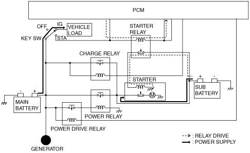
Two-battery power supply system
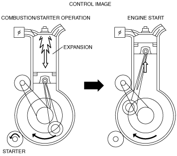
Engine start
am3zzn00002805
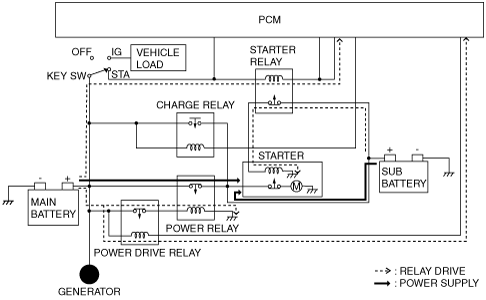
|
While driving
am3zzn00002806
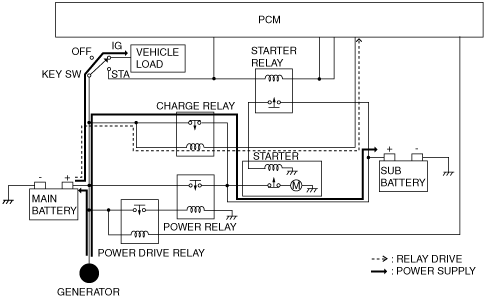
|
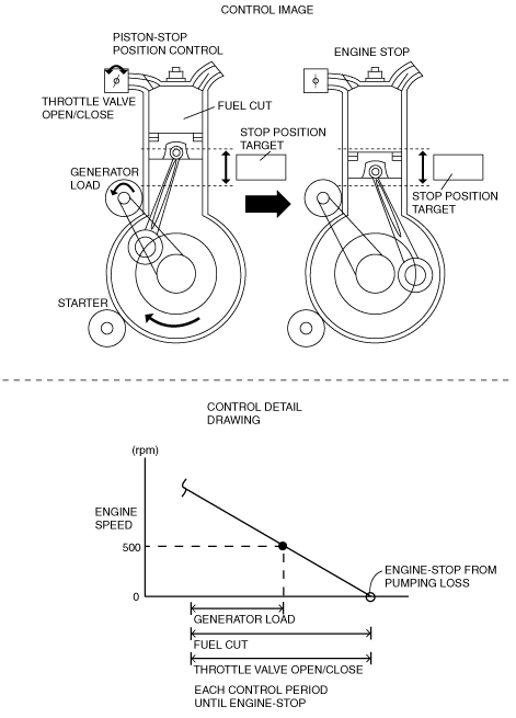
Engine stop control
am3zzn00002807
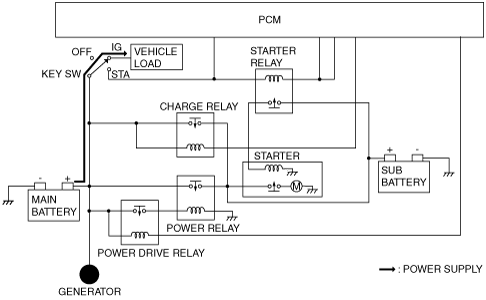
|
Engine restart control
am3zzn00002808
|
Sub battery malfunction
am3zzn00002809
|
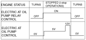
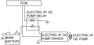
Electric AT oil pump driver control (ATX)
am3zzn00003151
|
System warning diagram
am3zzn00003152
|