STEP
INSPECTION
ACTION
1
CONFIRM ABS HU/CM DTC
• Retrieve the ABS HU/CM DTC using the M-MDS.
(See ON-BOARD DIAGNOSIS [ABS].)
• Are any DTCs present?
Yes
Go to the applicable DTC inspection.
(See ON-BOARD DIAGNOSIS [ABS].)
No
Inspect the instrument cluster.
If the instrument cluster is normal:
• Inspect CAN communication.
• Repair or replace the malfunctioning part according to the inspection results.
If the instrument cluster has a malfunction:
• Go to the next step.
2
VERIFY WHETHER MALFUNCTION IS IN WARNING LIGHTS AND INDICATOR LIGHT’S COMMON POWER SUPPLY, OR IN OTHER WARNING LIGHTS AND INDICATOR LIGHTS
• Do other warning and indicator lights illuminate when the ignition is switched to ON?
Yes
Replace the instrument cluster (open circuit in instrument cluster).
No
Go to the next step.
3
INSPECT INSTRUMENT CLUSTER POWER SUPPLY FUSE
• Switch the ignition to off.
• Disconnect the negative battery cable.
• Inspect the instrument cluster ignition power supply fuse.
• Is the fuse normal?
Yes
Go to the next step.
No
Inspect for short to ground in ignition power supply circuit.
Repair or replace if necessary.
Install appropriate amperage fuse.
*4
INSPECT INSTRUMENT CLUSTER POWER SUPPLY CIRCUIT FOR OPEN CIRCUIT
• Instrument cluster connector is disconnected.
• Reconnect the negative battery cable.
• Switch the ignition to ON.
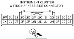
• Measure the voltage at instrument cluster terminal 2S (wiring harness-side).
• Is the voltage approx. 12 V?
Yes
Go to the next step.
No
Inspect for open circuit in wiring harness between instrument cluster and body ground.
If the wiring harness has a malfunction:
• Repair or replace the wiring harness.
If the wiring harness is normal:
• Replace the ABS CM.
5
INSPECT INSTRUMENT CLUSTER GROUND CIRCUIT FOR OPEN CIRCUIT
• Instrument cluster connector is disconnected.
• Switch the ignition to off.
• Disconnect the negative battery cable.
• Inspect for continuity between instrument cluster terminal 2A and body ground.
• Is there continuity?
Yes
Replace the instrument cluster (open circuit in instrument cluster).
No
Inspect and repair for followings:
• Open circuit in wiring between instrument cluster terminal 2A and body ground
• Poor installation of ground point