 |
am3zzw00007963
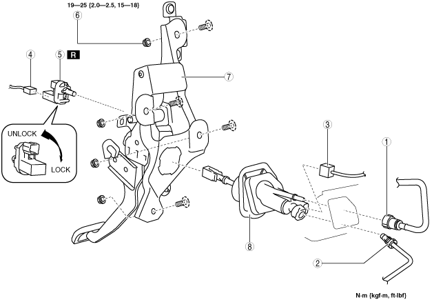
CLUTCH STROKE SENSOR REMOVAL/INSTALLATION [MZR 2.0 DISI i-stop]
id0510008030n4
1. Remove the battery cover. (See BATTERY REMOVAL/INSTALLATION [MZR 2.0 DISI i-stop].)
2. Disconnect the negative battery cable. (See BATTERY REMOVAL/INSTALLATION [MZR 2.0 DISI i-stop].)
3. Remove the battery and battery tray. (L.H.D.) (See BATTERY REMOVAL/INSTALLATION [MZR 2.0 DISI i-stop].)
4. Remove in the order indicated in the table.
5. Plug the clutch pipe after removing it to avoid leakage.
6. Install in the reverse order of removal.
7. Bleed the air from the system. (See CLUTCH FLUID AIR BLEEDING/REPLACEMENT.)
8. After installation, inspect the clutch pedal. (See CLUTCH PEDAL INSPECTION/ADJUSTMENT.)
L.H.D.
am3zzw00007963
|
R.H.D.
am3zzw00007964
|
|
1
|
Clutch reserve hose
|
|
2
|
Clutch pipe
|
|
3
|
Clutch stroke sensor connector
|
|
4
|
Clutch pedal position switch connector
|
|
5
|
Clutch pedal position switch
|
|
6
|
Nut
|
|
7
|
Clutch pedal component
|
|
8
|
Clutch stroke sensor
|
Clutch Pipe and Clutch Reserve Hose Removal Note
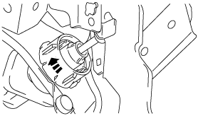
1. Remove the reserve hose from the reserve tank while pressing the point indicated by the arrow in the figure.
am3zzw00007965
|
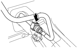
2. Remove the reserve hose from the clutch stroke sensor while pressing the point indicated by the arrow in the figure.
am3uuw00002104
|
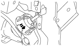
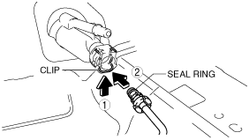
3. Pull the clutch stroke sensor clip to the position shown in the figure and pull out the clutch pipe connector straight to detach it.
am3uuw00002105
|
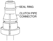
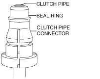
4. Verify that the seal ring is removed together with the clutch pipe connector.
am2zzw00003987
|
Clutch Stroke Sensor Removal Note
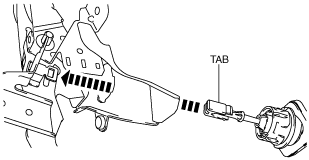
1. Rotate the clutch stroke sensor in the direction shown and remove.
am3uuw00002106
|
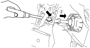
2. Press on the tabs on the left and right sides of the push rod using a flathead screwdriver and remove the rod.
am3uuw00002107
|
Clutch Stroke Sensor Installation Note
1. Push the push rod in until the tabs lock.
am3uuw00002108
|
2. Rotate the clutch stroke sensor in the direction shown until it stops.
am3uuw00002109
|
Clutch Pedal Position Switch Installation Note
1. Insert a new clutch pedal position switch into the pedal bracket hole until the switch stops.
am3zzw00005524
|
2. Rotate the clutch pedal position switch 45° clockwise.
am3uuw00000186
|
3. Verify that the clutch pedal position switch is locked securely.
Clutch Pipe and Clutch Reserve Hose Installation Note
1. Verify that the seal ring is assembled to the clutch pipe so that the ends of the seal ring and the clutch pipe overlap each other.
am2zzw00003960
|
2. Return the clutch stroke sensor clip to the position shown in the figure.
am3uuw00002110
|
3. Insert the clutch pipe connector straight.
4. Pull the clutch pipe to verify that it does not come off, and reinsert it completely.
5. Insert the reserve hose connector straight until a click is heard.
6. Pull the reserve hose to verify that it does not come off, and reinsert it completely.