 |
am3zzw00013485
BATTERY REMOVAL/INSTALLATION [MZR 2.0 DISI i-stop]
id011736800500
Operation After Connecting Negative Battery Cable
|
STEP |
ACTION |
NOTE |
|---|---|---|
|
1
|
Connect the negative battery cable.
|
|
|
2
|
Close the bonnet.
|
• Because the sub battery recharge is not available while the bonnet is open, the procedure is not completed.
|
|
3
|
Warm up the engine. (no electrical load)
|
|
|
4
|
Switch the ignition off.
|
|
|
5
|
Long-press the i-stop OFF switch for 3 s within 5 s after switching the ignition ON.
|
|
|
6
|
Start the engine.
|
|
|
7
|
Press the i-stop OFF switch.
Verify that the i-stop indicator light (green) flashes.
• If it does not flash, go back to Step 5.
|
|
|
8
|
Maintain the idle status (no electrical load) until the i-stop indicator light (green) turns off.
|
• For operating i-stop, learning is required for the following two items:
Initial learning/recharging for battery charge condition
ISC learning
• If the above two operations are successfully completed, the i-stop indicator light (green) turns off.
|
|
9
|
Verify that the engine stops via the i-stop control and then restarts.
• If it cannot be verified, inspect the i-stop system-related units for DTCs.
|
|
|
10
|
Switch the ignition off, and start the engine.
|
• The display function for the i-stop indicator light (green) is reset.
|
Operation After Replacing Main Battery
|
STEP |
ACTION |
NOTE |
|---|---|---|
|
1
|
Replace the main battery.
Verify the i-stop warning light (amber).
• If it flashes, go to the next step.
• If it does not flash, go to Step 3.
|
|
|
2
|
Clear applicable DTCs using the M-MDS.
|
|
|
3
|
Close the bonnet.
|
• Because the sub battery recharge is not available while the bonnet is open, the procedure is not completed.
|
|
4
|
Warm up the engine. (no electrical load)
|
|
|
5
|
Switch the ignition off.
|
|
|
6
|
Long-press the i-stop OFF switch for 3 s within 5 s after switching the ignition ON.
|
|
|
7
|
Start the engine.
|
|
|
8
|
Press the i-stop OFF switch.
Verify that the i-stop indicator light (green) flashes.
• If it does not flash, go back to Step 6.
|
|
|
9
|
Maintain the idle status (no electrical load) until the i-stop indicator light (green) turns off.
|
• For operating i-stop, learning is required for the following two items:
Initial learning/recharging for battery charge condition
ISC learning
• If the above two operations are successfully completed, the i-stop indicator light (green) turns off.
|
|
10
|
Verify that the engine stops via the i-stop control and then restarts.
• If it cannot be verified, inspect the i-stop system-related units for DTCs.
|
|
|
11
|
Switch the ignition off, and start the engine.
|
• The display function for the i-stop indicator light (green) is reset.
|
Operation After Replacing Sub-Battery
|
STEP |
ACTION |
NOTE |
|---|---|---|
|
1
|
Replace the sub-battery.
|
|
|
2
|
Reset the number of times the sub-battery can operate using the M-MDS.
Verify the i-stop warning light (amber).
• If it flashes, go to the next step.
• If it does not flash, go to Step 4.
|
|
|
3
|
Clear applicable DTCs using the M-MDS.
|
|
|
4
|
Close the bonnet.
|
• Because the sub battery recharge is not available while the bonnet is open, the procedure is not completed.
|
|
5
|
Warm up the engine. (no electrical load)
|
|
|
6
|
Switch the ignition off.
|
|
|
7
|
Long-press the i-stop OFF switch for 3 s within 5 s after switching the ignition ON.
|
|
|
8
|
Start the engine.
|
|
|
9
|
Press the i-stop OFF switch.
Verify that the i-stop indicator light (green) flashes.
• If it does not flash, go back to Step 7.
|
|
|
10
|
Maintain the idle status (no electrical load) until the i-stop indicator light (green) turns off.
|
• For operating i-stop, learning is required for the following two items:
Initial learning/recharging for battery charge condition
ISC learning
• If the above two operations are successfully completed, the i-stop indicator light (green) turns off.
|
|
11
|
Verify that the engine stops via the i-stop control and then restarts.
• If it cannot be verified, inspect the i-stop system-related units for DTCs.
|
|
|
12
|
Switch the ignition off, and start the engine.
|
• The display function for the i-stop indicator light (green) is reset.
|
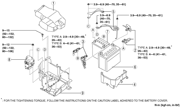
Battery Removal/Installation
1. Remove in the order indicated in the table.
2. Install in the reverse order of removal.
am3zzw00013485
|
|
1
|
Battery cover
(See Battery cover removal note.)
|
|
2
|
Negative battery cable
|
|
3
|
Positive battery cable
|
|
4
|
Battery box
|
|
5
|
Battery clamp
|
|
6
|
Main battery
(See Battery installation note.)
|
|
7
|
Sub battery
(See Battery installation note.)
|
|
8
|
Relay box
|
|
9
|
Battery tray
|
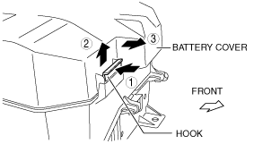
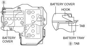
Battery cover removal note
1. Remove the battery cover using the following procedure.
am3zzw00013486
|
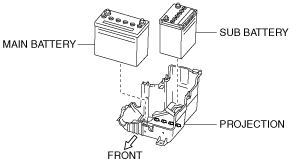
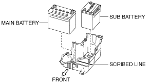
Battery installation note
am3zzw00013492
|
am3zzw00013493
|
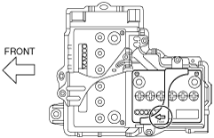
Battery clamp installation note
1. Assemble the battery clamp so that the arrow on it is pointed toward the front of the vehicle.
am3zzw00013487
|
Battery box installation note
1. Assemble with battery box holes A aligned with the battery tray tabs at two points.
am3zzw00013488
|
Battery cover installation note
1. Install with battery cover tab B aligned with the battery tray hook.
am3zzw00013489
|
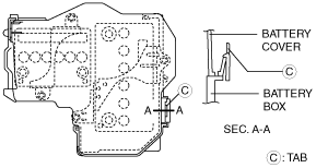
2. Install with battery cover tab C aligned with the battery box hole.
am3zzw00013490
|