 |
am3uuw00004040
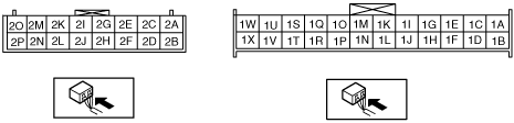
CLIMATE CONTROL UNIT INSPECTION [FULL-AUTO AIR CONDITIONER]
id0740a1802200
1. Remove the climate control unit with the connector connected. (See CLIMATE CONTROL UNIT REMOVAL/INSTALLATION [FULL-AUTO AIR CONDITIONER].)
2. Switch the ignition to ON.
3. Connect the negative (-) lead of the tester to body ground.
4. By inserting the positive (+) lead of the tester into each climate control unit terminal, measure the voltage according to the terminal voltage table.
Terminal Voltage Table (Reference)
am3uuw00004040
|
|
Terminal |
Signal name |
Connected to |
Measurement condition |
Voltage (V) |
Inspection item (s) |
|---|---|---|---|---|---|
|
1A*7
|
—
|
—
|
—
|
—
|
—
|
|
1A*8
|
R.H.D.
|
• Driver-side air mix actuator
• Passenger-side air mix actuator
• Airflow mode actuator
|
Under any condition
|
1.0 or less
|
• Related wiring harness
• Climate control unit: terminal voltage (1C)
|
|
1B
|
—
|
—
|
—
|
—
|
—
|
|
1C
|
+5V
|
• Driver-side air mix actuator
• Passenger-side air mix actuator
• Airflow mode actuator
• Solar radiation sensor
• Refrigerant pressure sensor*4
|
Switch the ignition to ON
|
5
|
• Related wiring harness
• Driver-side air mix actuator
• Passenger-side air mix actuator
• Airflow mode actuator
• Solar radiation sensor
• Refrigerant pressure sensor*4
• Climate control unit: terminal voltage (1E)
|
|
Switch the ignition to Off
|
1.0 or less
|
||||
|
1D
|
GND
|
Body ground
|
Under any condition
|
1.0 or less
|
• Related wiring harness
|
|
1E
|
Sensor GND
|
• Driver-side air mix actuator
• Passenger-side air mix actuator
• Airflow mode actuator
• Evaporator temperature sensor
• Refrigerant pressure sensor*4
• Heater core temperature sensor*6
|
Under any condition
|
1.0 or less
|
• Related wiring harness
• Climate control unit: terminal voltage (1C)
|
|
1F
|
Solar radiation sensor (RH) input
|
Solar radiation sensor
|
Sunlight shined directly on the solar radiation sensor
|
4
|
• Related wiring harness
• Climate control unit: terminal voltage (1C)
• Solar radiation sensor
|
|
Blocking light to solar radiation sensor
|
1.0 or less
|
||||
|
1G
|
Potentiometer input
|
Driver-side air mix actuator
|
Set temperature at MAX HOT
|
4.3 or more
|
• Related wiring harness
• Driver-side air mix actuator
• Climate control unit: terminal voltage (1C)
|
|
Set temperature at MAX COLD
|
1.0 or less
|
||||
|
1H
|
Solar radiation sensor (LH) input
|
Solar radiation sensor
|
Sunlight shined directly on the solar radiation sensor
|
4
|
• Related wiring harness
• Climate control unit: terminal voltage (1C)
• Solar radiation sensor
|
|
Blocking light to solar radiation sensor
|
1.0 or less
|
||||
|
1I
|
Potentiometer input
|
Passenger-side air mix actuator
|
Set temperature at MAX COLD
|
1.0 or less
|
• Related wiring harness
• Passenger-side air mix actuator
• Climate control unit: terminal voltage (1C)
|
|
Set temperature at MAX HOT
|
4.3 or more
|
||||
|
1J
|
—
|
—
|
—
|
—
|
—
|
|
1K
|
Potentiometer input
|
Airflow mode actuator
|
VENT
|
4.3 or more
|
• Related wiring harness
• Airflow mode actuator
• Climate control unit: terminal voltage (1C)
|
|
BI-LEVEL
|
3.4
|
||||
|
HEAT
|
2.5
|
||||
|
HEAT/DEF
|
1.6
|
||||
|
DEFROSTER
|
0.7 or less
|
||||
|
1L
|
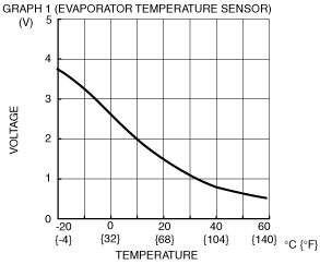
Evaporator temperature sensor input
|
Evaporator temperature sensor
|
Compared with temperature detected by evaporator temperature sensor
|
Refer to graph 1
|
• Related wiring harness
• Evaporator temperature sensor
• Climate control unit: terminal voltage (1E)
|
|
1M
|
Blower fan speed control
|
Power MOS FET
|
Fan stopped
|
1.0 or less
|
• Related wiring harness
• Power MOS FET
|
|
Fan: manual 1st
|
2.2
|
||||
|
Fan: manual 7th
|
9.7
|
||||
|
1N
|
Blower motor feedback
|
• Blower motor
• Power MOS FET
|
Fan stopped
|
B+
|
• Power MOS FET
• Blower motor
• Blower relay
• HEATER 40 A fuse
• Power MOS FET replacement
• Related wiring harness
|
|
Fan: manual 1st
|
9.8
|
||||
|
Fan: manual 7th
|
0.4 or less
|
||||
|
1O*5
|
—
|
—
|
—
|
—
|
—
|
|
1O*6
|
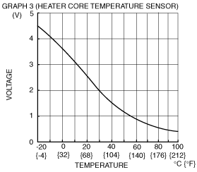
Heater core temperature sensor input
|
Heater core temperature sensor
|
Compared with temperature detected by heater core temperature sensor
|
Refer to graph 3
|
• Related wiring harness
• Heater core temperature sensor
• Climate control unit: terminal voltage (1E)
|
|
1P
|
—
|
—
|
—
|
—
|
—
|
|
1Q
|
Motor operation (COLD)
|
Passenger-side air mix actuator
|
Moving towards HOT
|
1.0 or less
|
• Related wiring harness
• Passenger-side air mix actuator
|
|
Moving towards COLD
|
B+
|
||||
|
1R
|
Motor operation (FRESH)
|
Air intake actuator
|
Moving towards RECIRCULATE
|
1.0 or less
|
• Related wiring harness
• Air intake actuator
|
|
Moving towards FRESH
|
B+
|
||||
|
1S
|
Motor operation (HOT)
|
Passenger-side air mix actuator
|
Moving towards HOT
|
B+
|
• Related wiring harness
• Passenger-side air mix actuator
|
|
Moving towards COLD
|
1.0 or less
|
||||
|
1T
|
Motor operation (RECIRCULATE)
|
Air intake actuator
|
Moving towards RECIRCULATE
|
B+
|
• Related wiring harness
• Air intake actuator
|
|
Moving towards FRESH
|
1.0 or less
|
||||
|
1U
|
Motor operation (COLD)
|
Driver-side air mix actuator
|
Moving towards HOT
|
1.0 or less
|
• Related wiring harness
• Driver-side air mix actuator
|
|
Moving towards COLD
|
B+
|
||||
|
1V
|
Motor operation (DEFROSTER)
|
Airflow mode actuator
|
Moving towards DEFROSTER
|
B+
|
• Related wiring harness
• Airflow mode actuator
|
|
Moving towards VENT
|
1.0 or less
|
||||
|
1W
|
Motor operation (HOT)
|
Driver-side air mix actuator
|
Moving towards HOT
|
B+
|
• Related wiring harness
• Driver-side air mix actuator
|
|
Moving towards COLD
|
1.0 or less
|
||||
|
1X
|
Motor operation (VENT)
|
Airflow mode actuator
|
Moving towards VENT
|
B+
|
• Related wiring harness
• Airflow mode actuator
|
|
Moving towards DEFROSTER
|
1.0 or less
|
||||
|
2A
|
Illumination control
|
Instrument cluster
|
Headlight switch ON and panel light control switch at MAX
|
1.0 or less
|
• Related wiring harness
• Instrument cluster
|
|
Headlight switch ON and panel light control switch at MIN
|
11.5
|
||||
|
2B
|
B+
|
ROOM 15 A fuse
|
Under any condition
|
B+
|
• Related wiring harness
• ROOM 15 A fuse
|
|
2C*3
|
+5V
|
Refrigerant pressure sensor
|
Switch the ignition to ON
|
5
|
• Related wiring harness
• Refrigerant pressure sensor
• Climate control unit: terminal voltage (2N)
|
|
Switch the ignition to Off
|
1.0 or less
|
||||
|
2D
|
—
|
—
|
—
|
—
|
—
|
|
2E
|
MS_CAN_H
|
CAN related module
|
Because this terminal is for communication, good/no good judgment by terminal voltage is not possible.
|
• Related wiring harness
|
|
|
2F
|
TNS signal
|
TNS relay
|
Headlight switch ON
|
B+
|
• Related wiring harness
• TNS relay
• BCM
• Headlight switch
|
|
Headlight switch OFF
|
1.0 or less
|
||||
|
2G
|
MS_CAN_L
|
CAN related module
|
Because this terminal is for communication, good/no good judgment by terminal voltage is not possible.
|
• Related wiring harness
|
|
|
2H
|
IG2
|
HEATER 10 A fuse
|
Switch the ignition to ON
|
B+
|
• Related wiring harness
• HEATER 10 A fuse
|
|
Switch the ignition to Off
|
1.0 or less
|
||||
|
2I*1
|
—
|
—
|
—
|
—
|
—
|
|
2I*2
|
Heated windshield signal
|
Heated windshield relay
|
Engine ON and heated windshield switch OFF
|
B+
|
• Related wiring harness
• Heated windshield relay
|
|
Engine ON and approx. 5 s after heated windshield switch ON
|
1.0 or less
|
||||
|
2J
|
Refrigerant pressure sensor input
|
Refrigerant pressure sensor
|
Compared with temperature detected by refrigerant pressure sensor
|
• Related wiring harness
• Refrigerant pressure sensor
• Climate control unit: terminal voltage (2C, 2N)*3 (1C, 1E)*4
|
|
|
2K
|
—
|
—
|
—
|
—
|
—
|
|
2L
|
—
|
—
|
—
|
—
|
—
|
|
2M
|
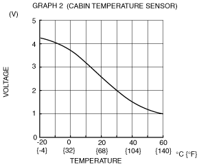
Cabin temperature sensor input
|
Cabin temperature sensor
|
Compared with temperature detected by cabin temperature sensor
|
Refer to graph 2
|
• Related wiring harness
• Cabin temperature sensor
• Climate control unit: terminal voltage (2N)
|
|
2N
|
Cabin temperature sensor GND
|
• Cabin temperature sensor
• Refrigerant pressure sensor*3
|
Under any condition
|
1.0 or less
|
• Climate control unit: terminal voltage (2M, 2C)
|
|
2O
|
—
|
—
|
—
|
—
|
—
|
|
2P
|
—
|
—
|
—
|
—
|
—
|
 |
 |
 |