SAS CONTROL MODULE REMOVAL/INSTALLATION
id081000801400
-
Warning
-
• Handling the SAS control module or air bag module improperly can accidentally deploy the air bag modules and pre-tensioner seat belt, which may seriously injure you. Read the air bag system service warnings and cautions before handling the air bag module. (See
AIR BAG SYSTEM SERVICE WARNINGS.) (See
AIR BAG SYSTEM SERVICE CAUTIONS.)
• If the connector is connected and the ignition switch is turned to the ON position with the SAS control module not secured completely using the installation nuts, the SAS control module may detect a degree of impact even when something contacts it lightly, deploying the air bag module and pre-tensioner seat belt accidentally.
• If the DSC sensor initialization procedure is not completed, it could result in an unexpected accident due to the DSC being inoperative. Therefore, after the SAS control module is replaced, always perform the DSC sensor initialization procedure to ensure proper DSC operation. (TYPE B: vehicles with DSC)
-
Caution
-
• When replacing the SAS control module, always perform the configuration procedure before removing the SAS control module. If the configuration is not performed and the SAS control module is removed, DTC B2477 will be displayed.
-
Note
-
• The SAS control module type differs depending on whether the DSC combined sensor is integrated.
-
― Type A: Separate combined sensor (3 module connectors)
― Type B: Built-in combined sensor (2 module connectors)
TYPE A
1. Perform SAS control module configuration when replacing it. (See SAS CONTROL MODULE CONFIGURATION.)
2. Switch the ignition to off.
3. Disconnect the negative battery cable and wait for 1 min or more.
4. Remove the following parts:
- (1) Upper panel (See UPPER PANEL REMOVAL/INSTALLATION.)
- (2) Shift lever knob (MTX) (See MANUAL TRANSAXLE SHIFT MECHANISM REMOVAL/INSTALLATION.)
- (3) Selector lever knob (ATX/CVT) (See AUTOMATIC TRANSAXLE SHIFT MECHANISM REMOVAL/INSTALLATION.) (See CVT (CONTINUOUSLY VARIABLE TRANSAXLE) SHIFT MECHANISM REMOVAL/INSTALLATION.)
- (4) Shift panel (See SHIFT PANEL REMOVAL/INSTALLATION.)
- (5) Side wall (See SIDE WALL REMOVAL/INSTALLATION.)
- (6) Center panel (See CENTER PANEL REMOVAL/INSTALLATION.)
- (7) Console (See CONSOLE REMOVAL/INSTALLATION.)
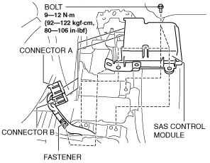
5. Detach the fastener.
6. Disconnect the connectors.
7. Remove the bolts.
8. Remove the SAS control module.
9. Install in the reverse order of removal.
10. Switch the ignition to ON.
11. Verify that the air bag system warning light illuminates for approx. 6 s and goes out.
-
• If the air bag system warning light does not operate normally, refer to the on-board diagnostic system (air bag system) and perform inspection of the system. (See
FLOWCHART [TYPE A].)
TYPE B
1. Perform SAS control module configuration when replacing it. (See SAS CONTROL MODULE CONFIGURATION.)
2. Switch the ignition to off.
3. Disconnect the negative battery cable and wait for 1 min or more.
4. Remove the following parts:
- (1) Upper panel (See UPPER PANEL REMOVAL/INSTALLATION.)
- (2) Shift lever knob (MTX) (See MANUAL TRANSAXLE SHIFT MECHANISM REMOVAL/INSTALLATION.)
- (3) Selector lever knob (ATX/CVT) (See AUTOMATIC TRANSAXLE SHIFT MECHANISM REMOVAL/INSTALLATION.) (See CVT (CONTINUOUSLY VARIABLE TRANSAXLE) SHIFT MECHANISM REMOVAL/INSTALLATION.)
- (4) Shift panel (See SHIFT PANEL REMOVAL/INSTALLATION.)
- (5) Side wall (See SIDE WALL REMOVAL/INSTALLATION.)
- (6) Center panel (See CENTER PANEL REMOVAL/INSTALLATION.)
- (7) Console (See CONSOLE REMOVAL/INSTALLATION.)
5. Detach the fastener.
6. Disconnect the connector A. (See Connector A connection note.)
7. Disconnect the connector B.
8. Remove the bolts.
9. Remove the SAS control module.
10. Install in the reverse order of removal.
11. Switch the ignition to ON.
12. Verify that the air bag system warning light illuminates for approx. 6 s and goes out.
-
• If the air bag system warning light does not operate normally, refer to the on-board diagnostic system (air bag system) and perform inspection of the system. (See
FLOWCHART [TYPE B].)
13. Perform the DSC sensor initialization procedures. (See DSC SENSOR INITIALIZATION PROCEDURE.)(vehicles with DSC)
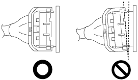
Connector A connection note
1. Verify that the connector A lever is tilted towards the wiring harness side as shown in the figure.
2. Insert the connector A straight until it contacts the SAS control module and verify that the lever reverts upward naturally.
-
Caution
-
• If the connector A is inserted at an angle and the lever is moved, the connector could be damaged. Verify that the connector A is inserted straight.
3. Push the lever until a click is heard.