 |
am3zzw00008733
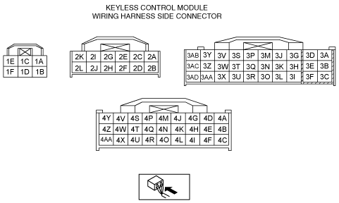
KEYLESS CONTROL MODULE INSPECTION [R.H.D.]
id0914005139d2
1. Remove the following parts:
2. Set the bonnet release lever out of the way. (See BONNET LATCH AND RELEASE LEVER REMOVAL/INSTALLATION.)
3. Remove the lower panel. (driver-side) (See LOWER PANEL REMOVAL/INSTALLATION.)
4. Measure the voltage according to the terminal voltage table.
Terminal Voltage Table (Reference)
am3zzw00008733
|
|
Terminal |
Signal name |
Connected to |
Measurement condition |
Voltage (V) |
Inspection item (s) |
||
|---|---|---|---|---|---|---|---|
|
1A
|
Power supply
|
ESCL15 A fuse
|
Under any condition
|
B+
|
ESCL15 A fuse
Battery
|
||
|
1B
|
GND
|
Body ground
|
Under any condition
|
1.0 or less
|
Body ground
|
||
|
1C
|
Power supply
|
Steering lock unit
|
Steering lock unit During lock/unlock control
|
B+
|
Steering lock unit
|
||
|
Other
|
1.0 or less
|
||||||
|
1D
|
Steering lock unit ground
|
Steering lock unit
|
Steering lock unit During lock/unlock control
|
1.0 or less
|
Steering lock unit
|
||
|
Other
|
2.7 (Typical)
|
||||||
|
1E
|
Power supply
|
ROOM 15 A fuse
|
Under any condition
|
B+
|
ROOM 15 A fuse
Battery
BCM
|
||
|
1F
|
Power supply
|
ENG+B 10 A fuse
|
Under any condition
|
B+
|
ENG+B 10 A fuse
Battery
|
||
|
2A
|
Power supply
|
METER 15 A fuse
|
Switch the ignitions to ON
|
B+
|
IG1 relay
METER 15 A fuse
Battery
|
||
|
Switch the ignitions to off or ACC
|
1.0 or less
|
||||||
|
2B
|
Push button start
|
Push button start
|
Push button start is pushed
|
1.0 or less
|
Push button start
|
||
|
Push button start is not pushed
|
B+
|
||||||
|
2C
|
Power supply
|
MIRROR 10 A fuse
|
Switch the ignitions to ACC
|
B+
|
ACC relay
MIRROR 10 A fuse
Battery
|
||
|
Switch the ignitions to off
|
1.0 or less
|
||||||
|
2E
|
Power supply
|
HEATER 10 A fuse
|
Switch the ignitions to ON
|
B+
|
IG2 relay
HEATER 10 A fuse
Battery
|
||
|
Switch the ignitions to off or ACC
|
1.0 or less
|
||||||
|
2F
|
Starter monitor (MTX)
|
Starter relay
|
Switch the ignitions to off
|
Clutch pedal is not depressed
|
Wave pattern 1 (See. Pattern 1)
|
Starter relay
|
|
|
Clutch pedal is depressed
|
Wave pattern 2 (See.Pattern 2)
|
||||||
|
Switch the ignitions to ON
|
Clutch pedal is not depressed
|
B+
|
|||||
|
Clutch pedal is depressed
|
1.0 or less
|
||||||
|
Starter monitor (ATX)
|
Starter relay
|
Switch the ignitions to off
|
Shift position is not P or N range
|
Wave pattern 1 (See. Pattern 1)
|
|||
|
Shift position is P or N range
|
Wave pattern 2 (See. Pattern 2)
|
||||||
|
Switch the ignitions to ON
|
Shift position is not P or N range
|
B+
|
|||||
|
Shift position is P or N range
|
1.0 or less
|
||||||
|
2G
|
Tx-PATS
|
Coil antenna
|
Communication lines, cannot be determined by voltage only (B+ when not communicating)
|
B+
|
Coil antenna
|
||
|
2H
|
Rx-PATS
|
Coil antenna
|
Communication lines, cannot be determined by voltage only (B+ when not communicating)
|
B+
|
Coil antenna
|
||
|
2I
|
Steering lock unit communication
|
Steering lock unit
|
Terminal used for communication therefore determination based on terminal voltage inspection not possible.
|
||||
|
2K
|
HS-CAN+
|
-
|
Terminal used for communication therefore determination based on terminal voltage inspection not possible.
|
||||
|
2L
|
HS-CAN-
|
-
|
Terminal used for communication therefore determination based on terminal voltage inspection not possible.
|
||||
|
3B
|
Starter relay (MTX)
|
Starter relay
|
Cranking
|
B+
|
Starter relay
|
||
|
Switch the ignitions to off
|
Clutch pedal is not depressed
|
Wave pattern 1 (See. Pattern 1)
|
|||||
|
Clutch pedal is depressed
|
Wave pattern 2 (See. Pattern 2)
|
||||||
|
Switch the ignitions to ON
|
Clutch pedal is not depressed
|
B+
|
|||||
|
Clutch pedal is depressed
|
1.0 or less
|
||||||
|
Starter relay (ATX)
|
Starter relay
|
Cranking
|
B+
|
||||
|
Switch the ignitions to off
|
Shift position is not P or N range
|
Wave pattern 1 (See. Pattern 1)
|
|||||
|
Shift position is P or N range
|
Wave pattern 2 (See. Pattern 2)
|
||||||
|
Switch the ignitions to ON
|
Shift position is not P or N range
|
B+
|
|||||
|
Shift position is P or N range
|
1.0 or less
|
||||||
|
3C
|
GND
|
Body ground
|
Under any condition
|
1.0 or less
|
Body ground
|
||
|
3D
|
IG 1 relay control
|
IG 1 Relay
|
Switch the ignitions to ON
|
B+
|
IG 1 Relay
|
||
|
Switch the ignitions to off or ACC
|
1.0 or less
|
||||||
|
3F
|
Push button illumination (ON)
|
Push button start
|
Switch the ignitions to off
|
Clutch pedal (MTX)/Brake pedal (ATX) is depressed
|
1.0 or less
|
Push button start
|
|
|
Push button start is pushed
|
|||||||
|
3G
|
IG 2 relay control
|
IG 2 Relay
|
Switch the ignitions to ON
|
B+
|
IG 2 Relay
|
||
|
Switch the ignitions to off or ACC
|
1.0 or less
|
||||||
|
3H
|
Push button illumination (Umber)
|
Push button start
|
System is malfunctioning
|
1.0 or less
|
Push button start
|
||
|
Other
|
B+
|
||||||
|
3I
|
Push button illumination (green)
|
Push button start
|
Engine start is available
|
1.0 or less
|
Push button start
|
||
|
Other
|
B+
|
||||||
|
3J
|
ACC relay control
|
ACC Relay
|
Switch the ignitions to ACC
|
B+
|
ACC Relay
|
||
|
Switch the ignitions to off
|
1.0 or less
|
||||||
|
3K
|
Push button illumination (ACC)
|
Push button start
|
In the case of ACC
|
1.0 or less
|
Push button start
|
||
|
Case except the ACC
|
B+
|
||||||
|
3M
|
Power supply
|
Coil antenna
|
Communication lines, cannot be determined by voltage only (B+ when not communicating)
|
B+
|
Coil antenna
|
||
|
3N
|
Ignition key illumination control
|
Coil antenna
|
Terminal used for communication therefore determination based on terminal voltage inspection not possible.
|
||||
|
3O*1
|
Starter interlock switch
|
Starter interlock switch
|
Clutch pedal is not depressed
|
B+
|
Starter interlock switch
|
||
|
Clutch pedal is depressed
|
1.0 or less
|
||||||
|
3Q
|
Push button start
|
Push button start
|
Push button start is pushed
|
1.0 or less
|
Push button start
|
||
|
Push button start is not pushed
|
B+
|
||||||
|
3R
|
Brake switch
|
Brake switch
|
Brake pedal is depressed
|
B+
|
Brake switch
|
||
|
Brake pedal is not depressed
|
1.0 or less
|
||||||
|
3S*2
|
P position
|
P position switch
|
Shift position is P
|
B+
|
P position switch
|
||
|
Other
|
1.0 or less
|
||||||
|
3T
|
Starter cut relay
(MTX)
|
Starter cut relay
|
Switch the ignitions to off
|
Clutch pedal is depressed
|
Wave pattern 2 (See. Pattern 2)
|
Starter cut relay
|
|
|
Clutch pedal is not depressed
|
1.0 or less
|
||||||
|
TR switch
(ATX)
|
TR switch
|
Shift position is P or N range
|
Wave pattern 2 (See. Pattern 2)
|
TR switch
|
|||
|
Shift position is not P or N range
|
1.0 or less
|
||||||
|
3U
|
Key reminder switch signal
|
Key reminder switch
|
Key inserted in steering lock
|
B+
|
Key reminder switch
|
||
|
Other
|
1.0 or less
|
||||||
|
3V
|
Power supply
|
Keyless receiver
|
Under any condition
|
B+
|
Keyless receiver
|
||
|
3W
|
Keyless entry communication
|
Keyless receiver
|
Terminal used for communication therefore determination based on terminal voltage inspection not possible.
|
||||
|
3X
|
BCM communication
|
BCM
|
Communication lines, cannot be determined by voltage only (B+ when not communicating)
|
B+
|
BCM
|
||
|
3Y*4
|
Keyless antenna (interior, glove compartment)
|
Keyless antenna (interior, glove compartment)
|
Terminal used for communication therefore determination based on terminal voltage inspection not possible.
|
||||
|
3Z
|
Keyless antenna (interior, front)
|
Keyless antenna (interior, front)
|
Terminal used for communication therefore determination based on terminal voltage inspection not possible.
|
||||
|
3AA
|
Keyless entry communication
|
Keyless receiver
|
Terminal used for communication therefore determination based on terminal voltage inspection not possible.
|
||||
|
3AB*4
|
Keyless antenna (interior, glove compartment)
|
Keyless antenna (interior, glove compartment)
|
Terminal used for communication therefore determination based on terminal voltage inspection not possible.
|
||||
|
3AC
|
Keyless antenna (interior, front)
|
Keyless antenna (interior, front)
|
Terminal used for communication therefore determination based on terminal voltage inspection not possible.
|
||||
|
3AD
|
GND
|
Body ground
|
Under any condition
|
1.0 or less
|
Body ground
|
||
|
4A
|
Keyless antenna (RF)
|
Keyless antenna (RF)
|
Terminal used for communication therefore determination based on terminal voltage inspection not possible.
|
||||
|
4B
|
Keyless antenna (LF)
|
Keyless antenna (LF)
|
Terminal used for communication therefore determination based on terminal voltage inspection not possible.
|
||||
|
4C
|
Keyless antenna (exterior, rear)
|
Keyless antenna (exterior, rear)
|
Terminal used for communication therefore determination based on terminal voltage inspection not possible.
|
||||
|
4D
|
Keyless antenna (RF)
|
Keyless antenna (RF)
|
Terminal used for communication therefore determination based on terminal voltage inspection not possible.
|
||||
|
4E
|
Keyless antenna (LF)
|
Keyless antenna (LF)
|
Terminal used for communication therefore determination based on terminal voltage inspection not possible.
|
||||
|
4F
|
Keyless antenna (exterior, rear)
|
Keyless antenna (exterior, rear)
|
Terminal used for communication therefore determination based on terminal voltage inspection not possible.
|
||||
|
4G
|
Keyless antenna (interior, rear)
|
Keyless antenna (interior, rear)
|
Terminal used for communication therefore determination based on terminal voltage inspection not possible.
|
||||
|
4I
|
GND
|
Body ground
|
Under any condition
|
1.0 or less
|
Body ground
|
||
|
4J
|
Keyless antenna (interior, rear)
|
Keyless antenna (interior, rear)
|
Terminal used for communication therefore determination based on terminal voltage inspection not possible.
|
||||
|
4L
|
Keyless beeper power supply
|
Keyless beeper
|
Exterior keyless beeper sounds
|
5.0 or more
|
Keyless beeper
|
||
|
Other
|
1.0 or less
|
||||||
|
4O
|
Request switch input
(passenger's door)
|
Request switch (RF)
|
Passenger's side request switch ON
|
1.0 or less
|
Front outer handle (passenger's door)
|
||
|
Passenger's side request switch OFF
|
4.0 or more
|
||||||
|
4R
|
Request switch input
(driver's door)
|
Request switch (LF)
|
Driver's side request switch ON
|
1.0 or less
|
Front outer handle (driver's door)
|
||
|
Driver's side request switch OFF
|
4.0 or more
|
||||||
|
4S
|
Trunk lid/liftgate release input
|
Trunk lid/liftgate opener switch
|
Trunk lid/liftgate opener switch pressed
|
3.0 or more
|
Trunk lid opener switch
Liftgate opener switch
|
||
|
Trunk lid/liftgate opener switch released
|
1.0 or less
|
||||||
|
4T*3
|
Request switch input
(Liftgate)
|
Request switch (Liftgate)
|
Liftgate request switch ON
|
1.0 or less
|
Request switch (Liftgate)
|
||
|
Liftgate request switch OFF
|
4.0 or more
|
||||||
|
4U
|
Lock input
|
Door lock-link switch (driver's door)
|
Driver's side door lock switch at LOCK
|
1.0 or less
|
Door lock-link switch
|
||
|
Driver's side door lock switch at UNLOCK
|
Wave pattern (See Pattern 3.)
|
||||||
|
4V*1
|
Clutch pedal position switch
|
Clutch pedal position switch
|
Clutch pedal is depressed
|
1.0 or less
|
Clutch pedal position switch
|
||
|
Clutch pedal is not depressed
|
B+
|
||||||
|
4W
|
Brake switch
|
Brake switch
|
Brake pedal is depressed
|
B+
|
Brake switch
|
||
|
Brake pedal is not depressed
|
1.0 or less
|
||||||
|
4X*1
|
Neutral switch
|
Neutral switch
|
Shift lever is in neutral position
|
1.0 or less
|
Neutral switch
|
||
|
Shift lever is not in neutral position
|
B+
|
||||||
|
4Z
|
GND
|
Keyless beeper
|
Under any condition
|
1.0 or less
|
Keyless beeper
|
||
|
4AA
|
GND
|
Body ground
|
Under any condition
|
1.0 or less
|
Body ground
|
||
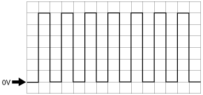
Generated pulse (reference)
Pattern 1
am3uuw00006333
|
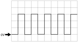
Pattern 2
am3zzw00009212
|
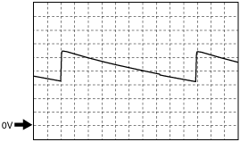
Pattern 3
aatjjw00004591
|