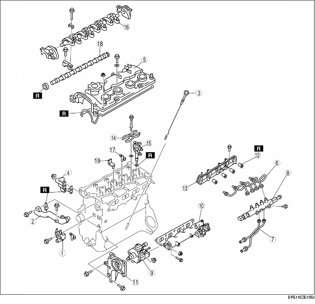
1. Disassemble in the order indicated in the table.
|
1
|
No.3 engine mount bracket
|
|
2
|
Water outlet
|
|
3
|
Dipstick
|
|
4
|
Bypass pipe
|
|
5
|
Cylinder head cover (See Cylinder Head Cover Disassembly Note)
|
|
6
|
injection pipe (Fuel injector side)
|
|
7
|
injection pipe (Supply pump side)
|
|
8
|
Common rail
|
|
9
|
Supply pump
|
|
10
|
Intake manifold
|
|
11
|
Supply pump bracket
|
|
12
|
Nozzle seal
|
|
13
|
Side wall
|
|
14
|
Fuel injector bracket
|
|
15
|
Fuel injector
|
|
16
|
Rocker arm and rocker arm shaft
|
|
17
|
Rocker bridge
|
|
18
|
Camshaft
|
|
19
|
Breather pipe
|
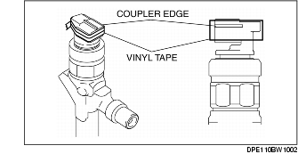
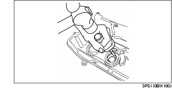
1. Wrap the fuel injector coupler with vinyl tape 2 times covering the coupler edge so as not to damage the injector seal.
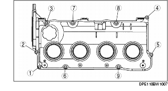
2. Loosen the bolts in the order shown in the figure.
3. Remove the cylinder head cover carefully so as not to damage the injector seal from coupler edge.
4. Verify that there are no cracks or rips on the injector seal.
5. If there are any cracks or rips, remove the injector seal using the following procedure to replace it with a new one.
1. Inspect the camshaft end play.
(See CAMSHAFT END PLAY INSPECTION [WITH DIESEL PARTICULATE FILTER])
2. Inspect the camshaft oil clearance.
(See CAMSHAFT OIL CLEARANCE INSPECTION [WITH DIESEL PARTICULATE FILTER])
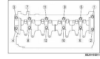
3. Loosen the bolts in two or three steps in the order shown.