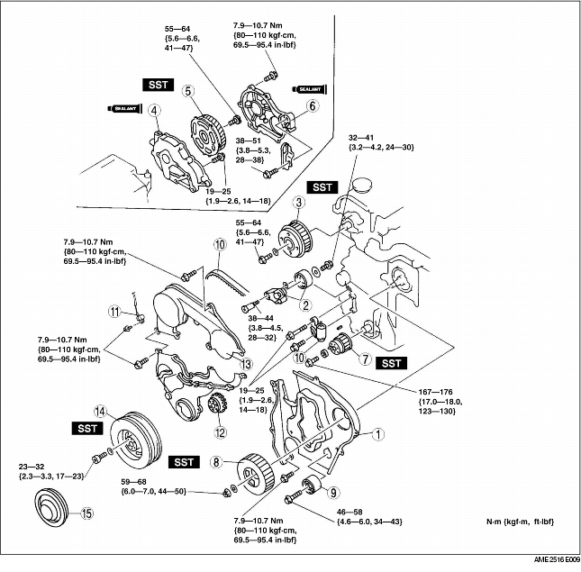
1. Assemble in the order indicated in the table.
|
1
|
Seal plate
(See Seal Plate Assembly Note)
|
|
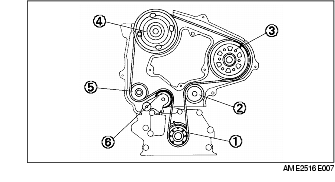
2
|
Tensioner
|
|
3
|
Camshaft pulley
|
|
4
|
Gear case
(See Gear Case Assembly Note)
|
|
5
|
Drive gear
(See Drive Gear Assembly Note)
|
|
6
|
Gear cover
(See Gear Cover Assembly Note)
|
|
7
|
Timing belt pulley
|
|
8
|
Injection pump pulley
|
|
9
|
Idler (See Idler Assembly Note)
|
|
10
|
Timing belt, timing belt auto tensioner
|
|
11
|
Crankshaft position sensor
|
|
12
|
Guide plate
|
|
13
|
Timing belt cover
|
|
14
|
Crankshaft pulley
|
|
15
|
Pulley cover
|
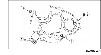
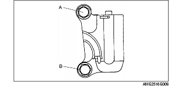
1. Install the seal plate and hand tighten the bolts in the order A to B.
2. Tighten the bolts in the order shown.
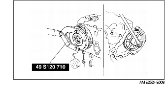
1. Hold the camshaft using the SST.
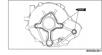
1. Apply silicone sealant as shown in the figure.
2. Tighten the bolts in clockwise order.
1. Hold the camshaft using the SST.
2. Remove the drive gear lock bolt.
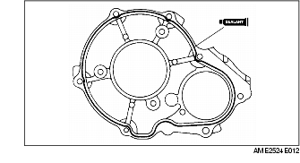
1. Apply silicone sealant as shown in the figure.
2. Tighten the bolts in clockwise order.
1. Hold the crankshaft using the SST.
2. Tighten the timing belt pulley lock bolt.
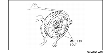
1. Fix the injection pump pulley to the bracket using two bolts (M8 x 1.25).
1. Verify the thrust of the auto tensioner rod in the following order:
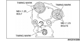
2. Verify that all timing marks are correctly aligned.
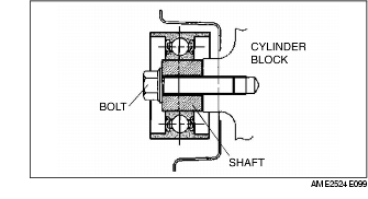
3. Fix the camshaft pulley to the cylinder head using bolt (M8 x 1.25).
4. Fix the injection pump pulley to the bracket using two bolts (M8 x 1.25).
5. If not, align all timing marks according to the following procedure.
6. Install the timing belt on the pulleys in the following order.
7. Remove the injection pump pulley fixing bolts and camshaft pulley fixing bolt (M8 x 1.25).
8. Hand-tighten the auto tensioner bolts in the order A to B.
9. Tighten the auto tensioner bolts in the order A to B.
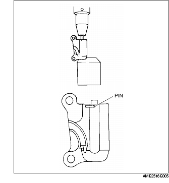
10. Remove the pin from the auto tensioner to apply tension to the belt.
11. Turn the crankshaft clockwise twice, and align the timing marks.
12. Verify that all timing marks are correctly aligned. If not, repeat from Timing Belt, Timing Belt Auto Tensioner Removal Note.
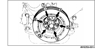
1. Hold the crankshaft using the SST.
2. Tighten the bolts in the order shown.