 |
baf4za00000062
SECONDARY GEAR BEARING PRELOAD
id051700116800
1. Assemble the primary gear. (See AUTOMATIC TRANSAXLE ASSEMBLY.)
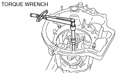
2. Measure the primary gear bearing preload.
baf4za00000062
|
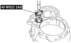
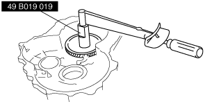
3. Remove the bearing race and adjustment shim from the converter housing using the SST.
baf4za00000115
|
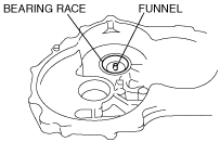
4. Install the funnel and bearing race to the transaxle case.
baf4za00000116
|
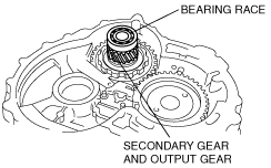
5. Install the the secondary gear and output gear to the transaxle case.
6. Install the bearing race removed in Step 3 to the secondary gear and output gear.
baf4za00000117
|
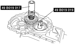
7. Set the SSTs on to the primary gear and the secondary gear and output gear.
baf4za00000118
|
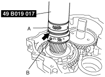
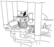
8. Rotate parts A and B of the SST and eliminate the gap indicated by the arrow in the figure.
baf4za00000119
|
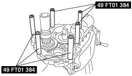
9. Install the SSTs (6 collars) in the positions shown in the figure.
baf4za00000120
|
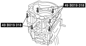
10. Set the converter housing on the transaxle case and tighten it using the SSTs (bolts).
baf4za00000121
|
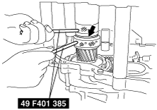
11. To allow the bearing to drop, widen the gap shown in the figure by rotating the SST (selector) until it no longer moves using the SSTs (bars).
baf4za00000122
|
12. Rotate the SST (selector) back and reduce the gap.
13. Insert the extension bar from the converter housing and install it to the SST (preload adapter).
14. Using the following formula, calculate the secondary gear and output gear bearing load adjustment value.
15. Adjust the SST (selector) clearance using the SSTs (bars) so that it is the preload adjustment is the value calculated in Step 14.
baf4za00000123
|
baf4za00000122
|
16. Measure the gap indicated by the arrow in the figure.
baf4za00000124
|
17. Select an adjustment shim which matches the gap measured in Step 16.
Secondary gear and output gear bearing preload-use adjustment shim
|
0.450 {0.0177}
|
0.475 {0.0187}
|
0.500 {0.0197}
|
|
0.525 {0.0207}
|
0.550 {0.0217}
|
0.575 {0.0226}
|
|
0.600 {0.0236}
|
0.625 {0.0246}
|
0.650 {0.0256}
|
|
0.675 {0.0266}
|
0.700 {0.0276}
|
0.725 {0.0285}
|
|
0.750 {0.0295}
|
0.775 {0.0305}
|
0.800 {0.0315}
|
|
0.825 {0.0325}
|
0.850 {0.0335}
|
0.875 {0.0344}
|
|
0.900 {0.0354}
|
0.925 {0.0364}
|
0.950 {0.0374}
|
|
0.975 {0.0384}
|
1.000 {0.03937}
|
1.025 {0.04035}
|
|
1.050 {0.04134}
|
1.075 {0.04232}
|
1.100 {0.04331}
|
|
1.125 {0.04429}
|
1.150 {0.04528}
|
1.175 {0.04626}
|
|
1.200 {0.04724}
|
1.225 {0.04823}
|
1.250 {0.04921}
|
18. Remove the SSTs and the converter housing.
19. Assemble the selected adjustment shim and bearing race to the converter housing.
baf4za00000125
|
20. Assemble the converter housing to the transaxle case.
21. Set the SST (preload adapter) on to the primary gear.
22. Insert the extension bar from the converter housing and install it to the SST (preload adapter).
23. Verify that the secondary gear and output gear bearing preload adjustment value is within the specification.
24. If not within the specification, repeat from Step 1.
25. Remove the converter housing.