|
1
|
VERIFY FREEZE FRAME DATA HAS BEEN RECORDED
• Has FREEZE FRAME PID DATA been recorded?
|
Yes
|
Go to the next step.
|
|
No
|
Record FREEZE FRAME PID DATA on repair order, then go to the next step.
|
|
2
|
VERIFY RELATED SERVICE INFORMATION AVAILABILITY
• Verify related Service Information availability.
• Is any related Service Information available?
|
Yes
|
Perform repair or diagnosis according to the available Service Information.
• If the vehicle is not repaired, go to the next step.
|
|
No
|
Go to the next step.
|
|
3
|
VERIFY CURRENT INPUT SIGNAL STATUS-IS CONCERN INTERMITTENT OR CONSTANT
• Connect the M-MDS to DLC-2.
• Start the engine.
• Access VSS PID using the M-MDS.
-
― Vehicle speed 20 km/h {12.4 mph}: 20km/h {12.4 mph}
― Vehicle speed 40 km/h {24.8 mph}: 40km/h {24.8 mph}
• Are PID readings within specification?
|
Yes
|
Go to intermittent concern troubleshooting procedure.
|
|
No
|
Go to the next step.
|
|
4
|
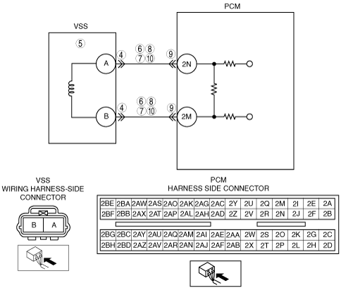
INSPECT VSS CONNECTOR FOR POOR CONNECTION
• Verify that the VSS connector is connected securely.
• Is connector normal?
|
Yes
|
Go to the next step.
|
|
No
|
Reconnect the connector, then go to Step 11.
|
|
5
|
INSPECT THE VSS
• Perform VSS inspection.
• Is the VSS normal?
|
Yes
|
Go to the next step.
|
|
No
|
Replace VSS, then go to Step 11.
|
|
6
|
INSPECT VSS CIRCUIT FOR SHORT TO POWER
• Turn the ignition switch off.
• Disconnect the VSS connector.
• Turn the ignition switch to the ON position (Engine off).
• Measure the voltage following terminals:
-
― VSS terminal A
― VSS terminal B
• Is any voltage reading?
|
Yes
|
Repair or replace suspected harness, then go to Step 11.
|
|
No
|
Go to the next step.
|
|
7
|
INSPECT VSS CIRCUIT FOR SHORT TO GROUND
• Inspect continuity between following terminal and body ground:
-
― VSS terminal A
― VSS terminal B
• Is there any continuity?
|
Yes
|
Repair or replace suspected harness, then go to Step 11.
|
|
No
|
Go to the next step.
|
|
8
|
INSPECT VSS CIRCUITS FOR SHORTS
• Inspect continuity between the VSS connector terminals A and B.
• Is there any continuity?
|
Yes
|
Repair or replace suspected harness, then go to Step 11.
|
|
No
|
Go to the next step.
|
|
9
|
INSPECT PCM CONNECTOR FOR POOR CONNECTION
• Disconnect the PCM connector.
• Inspect for poor connection (such as damaged/ pulled-out terminals, corrosion).
• Is there any malfunction?
|
Yes
|
Repair terminal, then go to Step 11.
|
|
No
|
Go to the next step.
|
|
10
|
INSPECT VSS CIRCUIT FOR OPEN CIRCUIT
• Inspect continuity between following terminals:
-
― VSS terminal A and PCM terminal 2N
― VSS terminal B and PCM terminal 2M
• Is there continuity?
|
Yes
|
Inspect VSS pulse wheel for damage. Replace VSS pulse wheel and go to the next step.
|
|
No
|
Repair or replace suspected harness, then go to the next step.
|
|
11
|
VERIFY TROUBLESHOOTING OF DTC P0500 COMPLETED
• Make sure to reconnect all disconnected connectors.
• Turn the ignition switch to the ON position (Engine off).
• Clear DTC from PCM memory using M-MDS.
• Warm up the engine.
• Access RPM and LOAD PID using M-MDS.
• Drive vehicle under following conditions for 18s.
-
― Engine speed: 2,000 rpm or above
― Gear: Gear is in other than NEUTRAL
― Load: 40% or above
• Is PENDING CODE for this DTC present?
|
Yes
|
Replace PCM, then go to the next step.
|
|
No
|
Go to the next step.
|
|
12
|
VERIFY AFTER REPAIR PROCEDURE
• Perform “AFTER REPAIR PROCEDURE”.
• Is there any DTC present?
|
Yes
|
Go to applicable DTC troubleshooting.
|
|
No
|
Troubleshooting completed.
|