|
1
|
VERIFY FREEZE FRAME DATA HAS BEEN RECORDED
• Has FREEZE FRAME PID DATA been recorded?
|
Yes
|
Go to the next step.
|
|
No
|
Record FREEZE FRAME PID DATA on repair order, then go to the next step.
|
|
2
|
VERIFY RELATED SERVICE INFORMATION AVAILABILITY
• Verify related Service Information availability.
• Is any related Service Information available?
|
Yes
|
Perform repair or diagnosis according to the available Service Information.
• If the vehicle is not repaired, go to the next step.
|
|
No
|
Go to the next step.
|
|
3
|
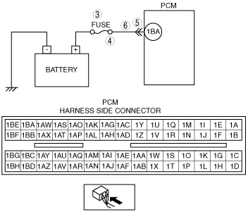
INSPECT FUSE
• Turn the ignition switch off.
• Inspect fuse for failure and proper.
• Is it normal?
|
Yes
|
Go to Step 6.
|
|
No
|
• If fuse has been burnt, then go to the next step.
• If fuse is not installed correctly, install it correctly then go to Step 7.
|
|
4
|
INSPECT MONITOR CIRCUIT FOR SHORT TO GROUND
• Disconnect battery cables.
• Inspect for continuity between fuse terminal and body ground.
• Is there continuity?
|
Yes
|
Repair or replace the wiring harness for short to ground and install new fuse, then go to Step 7.
|
|
No
|
Go to Step 7.
|
|
5
|
INSPECT PCM CONNECTOR FOR POOR CONNECTION
• Disconnect PCM connector.
• Inspect for poor connection (such as damaged, pulled-out terminals, corrosion).
• Is there any malfunction?
|
Yes
|
Repair terminals, then go to Step 7.
|
|
No
|
Go to the next step.
|
|
6
|
INSPECT MONITOR CIRCUIT FOR OPEN CIRCUIT
• Disconnect battery cables.
• Inspect for continuity between fuse terminal and PCM terminal 1BA.
• Is there continuity?
|
Yes
|
Go to the next step.
|
|
No
|
Repair or replace the wiring harness for open circuit, then go to the next step.
|
|
7
|
VERIFY TROUBLESHOOTING OF DTC P2507 COMPLETED
• Make sure to reconnect all disconnected connectors.
• Turn the ignition switch to the ON position (Engine off).
• Clear the DTC from the PCM memory using the M-MDS.
• Start the engine and warm it up completely.
• Is the same DTC present?
|
Yes
|
Replace the PCM, then go to the next step.
|
|
No
|
Go to the next step.
|
|
8
|
VERIFY AFTER REPAIR PROCEDURE
• Perform “AFTER REPAIR PROCEDURE”.
• Is any DTC present?
|
Yes
|
Go to the applicable DTC inspection.
|
|
No
|
Troubleshooting completed.
|