DTC P2008[ZJ, ZY, Z6]


id0102c1840100


Without Throttle Valve Actuator

DTC P2008

Variable tumble control circuit/open

DETECTION CONDITION
•  The PCM monitors the variable tumble control signal. If the PCM turns the variable tumble shutter valve actuator to open or close but voltages do not coincide with the PCM signal voltages the PCM determines that the variable tumble control circuit has a malfunction.
•  Variable tumble control IC error.
Diagnostic support note
•  This is a continuous monitor (CCM).
•  The MIL illuminates if the PCM detects the above malfunction condition in two consecutive drive cycles or in one drive cycle while the DTC for the same malfunction has been stored in the PCM.
•  PENDING CODE is available if the PCM detects the above malfunction condition during the first drive cycle.
•  FREEZE FRAME DATA is available.
•  The DTC is stored in the PCM memory.
POSSIBLE CAUSE
•  Variable tumble shutter valve actuator malfunction
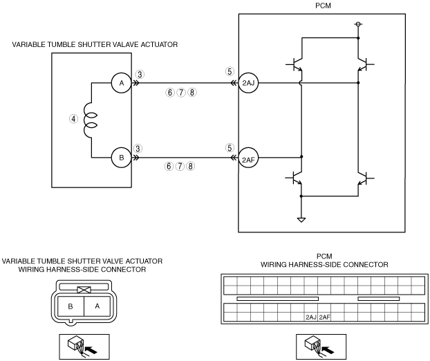
•  Short to power supply in wiring harness between variable tumble shutter valve actuator terminal A and PCM terminal 2AJ
•  Short to ground in wiring harness between variable tumble shutter valve actuator terminal A and PCM terminal 2AJ
•  Open circuit in wiring harness between variable tumble shutter valve actuator terminal A and PCM terminal 2AJ
•  Short to power supply in wiring harness between variable tumble shutter valve actuator terminal B and PCM terminal 2AF
•  Short to ground in wiring harness between variable tumble shutter valve actuator terminal B and PCM terminal 2AF
•  Open circuit in wiring harness between variable tumble shutter valve actuator terminal B and PCM terminal 2AF
•  Poor connection at variable tumble shutter valve actuator or PCM
•  PCM malfunction

Diagnostic procedure

STEP

INSPECTION

ACTION

1
VERIFY FREEZE FRAME DATA HAS BEEN RECORDED
•  Has FREEZE FRAME DATA been recorded?
Yes
Go to the next step.
No
Record the FREEZE FRAME DATA on the repair order, then go to the next step.
2
VERIFY RELATED SERVICE INFORMATION AVAILABILITY
•  Verify related Service Information availability.
•  Is any related Service Information available?
Yes
Perform repair or diagnosis according to the available Service Information.
•  If the vehicle is not repaired, go to the next step.
No
Go to the next step.
3
INSPECT VARIABLE TUMBLE SHUTTER VALVE ACTUATOR CONNECTOR FOR POOR CONNECTION
•  Turn the ignition switch off.
•  Disconnect the variable tumble shutter valve actuator connector.
•  Inspect for poor connection (such as damaged, pulled-out pins, and corrosion).
•  Is there any malfunction?
Yes
Repair or replace the terminal, then go to Step 9.
No
Go to the next step.
4
INSPECT VARIABLE TUMBLE SHUTTER VALVE ACTUATOR MALFUNCTION
•  Perform the variable tumble shutter valve actuator inspection.
•  Is the variable tumble shutter valve actuator normal?
Yes
Go to the next step.
No
Replace the variable tumble shutter valve actuator, then go to Step 9.
5
INSPECT PCM CONNECTOR FOR POOR CONNECTION
•  Turn the ignition switch off.
•  Disconnect the PCM connector.
•  Inspect for poor connection (such as damaged/pulled-out pins, corrosion).
•  Is there any malfunction?
Yes
Repair terminal, then go to Step 9.
No
Go to the next step.
6
INSPECT VARIABLE TUMBLE SHUTTER VALVE ACTUATOR CONTROL CIRCUIT FOR OPEN CIRCUIT
•  Inspect for continuity between followings;
―  Between variable tumble shutter valve actuator terminal A (wiring harness-side) and PCM terminal 2AJ (wiring harness-side)
―  Between variable tumble shutter valve actuator terminal B (wiring harness-side) and PCM terminal 2AF (wiring harness-side)
•  Is there continuity?
Yes
Go to the next step.
No
Repair or replace wiring harness for open circuit, then go to Step 9.
7
INSPECT VARIABLE TUMBLE SHUTTER VALVE ACTUATOR CONTROL CIRCUIT FOR SHORT TO GROUND
•  Inspect for continuity between followings;
―  Between variable tumble shutter valve actuator terminal A (wiring harness-side) and body ground
―  Between variable tumble shutter valve actuator terminal B (wiring harness-side) and body ground
•  Is there continuity?
Yes
Repair or replace for short to ground, then go to Step 9.
No
Go to the next step.
8
INSPECT VARIABLE TUMBLE SHUTTER VALVE ACTUATOR CONTROL CIRCUIT FOR SHORT TO POWER
•  Turn the ignition switch to the ON position. (Engine off).
•  Measure the voltage following terminals:
―  Variable tumble shutter valve actuator terminal A (wiring harness-side) and body ground
―  Variable tumble shutter valve actuator terminal B (wiring harness-side) and body ground
•  Is the terminal voltage B+?
Yes
Repair or replace for short to power supply, then go to the next step.
No
Go to the next step.
9
VERIFY TROUBLESHOOTING OF DTC P2008 COMPLETED
•  Make sure to reconnect all disconnected connectors.
•  Clear the DTC from the PCM memory using the M-MDS.
•  Start the engine.
•  Is the PENDING CODE for this DTC present?
Yes
Replace the PCM, then go to the next step.
No
Go to the next step.
10
VERIFY AFTER REPAIR PROCEDURE
•  Perform “AFTER REPAIR PROCEDURE”.
•  Are any DTCs present?
Yes
Go to the applicable DTC troubleshooting.
No
Troubleshooting completed.


With Throttle Valve Actuator

DTC P2008

Variable tumble control circuit malfunction

DETECTION CONDITION
•  The PCM monitors the variable tumble control signal. If the PCM turns the variable tumble shutter valve actuator to open or close but voltages do not coincide with the PCM signal voltages the PCM determines that the variable tumble control circuit has a malfunction.
•  Variable tumble control IC error.
Diagnostic support note
•  This is a continuous monitor (CCM).
•  The MIL illuminates if the PCM detects the above malfunction condition in two consecutive drive cycles or in one drive cycle while the DTC for the same malfunction has been stored in the PCM.
•  PENDING CODE is available if the PCM detects the above malfunction condition during the first drive cycle.
•  FREEZE FRAME DATA is available.
•  The DTC is stored in the PCM memory.
POSSIBLE CAUSE
•  Variable tumble shutter valve actuator malfunction
•  Connector or terminal malfunction
•  Short to power supply in wiring harness between variable tumble shutter valve actuator terminal B and PCM terminal 2AG
•  Short to ground in wiring harness between variable tumble shutter valve actuator terminal B and PCM terminal 2AG
•  Open circuit in wiring harness between variable tumble shutter valve actuator terminal B and PCM terminal 2AG
•  Short to power supply in wiring harness between variable tumble shutter valve actuator terminal D and PCM terminal 2AK
•  Short to ground in wiring harness between variable tumble shutter valve actuator terminal D and PCM terminal 2AK
•  Open circuit in wiring harness between variable tumble shutter valve actuator terminal D and PCM terminal 2AK
•  PCM malfunction

Diagnostic procedure

STEP

INSPECTION

ACTION

1
VERIFY FREEZE FRAME DATA HAS BEEN RECORDED
•  Has FREEZE FRAME DATA been recorded?
Yes
Go to the next step.
No
Record the FREEZE FRAME DATA on the repair order, then go to the next step.
2
VERIFY RELATED SERVICE INFORMATION AVAILABILITY
•  Verify related Service Information availability.
•  Is any related Service Information available?
Yes
Perform repair or diagnosis according to the available Service Information.
•  If the vehicle is not repaired, go to the next step.
No
Go to the next step.
3
INSPECT VARIABLE TUMBLE SHUTTER VALVE ACTUATOR CONNECTOR FOR POOR CONNECTION
•  Turn the ignition switch off.
•  Disconnect the variable tumble shutter valve actuator connector.
•  Inspect for poor connection (such as damaged, pulled-out pins, and corrosion).
•  Is there any malfunction?
Yes
Repair or replace the terminal, then go to Step 9.
No
Go to the next step.
4
INSPECT VARIABLE TUMBLE SHUTTER VALVE ACTUATOR MALFUNCTION
•  Perform the variable tumble shutter valve actuator inspection.
•  Is the variable tumble shutter valve actuator normal?
Yes
Go to the next step.
No
Replace the variable tumble shutter valve actuator, then go to Step 9.
5
INSPECT PCM CONNECTOR FOR POOR CONNECTION
•  Turn the ignition switch off.
•  Disconnect the PCM connector.
•  Inspect for poor connection (such as damaged/pulled-out pins, corrosion).
•  Is there any malfunction?
Yes
Repair terminal, then go to Step 9.
No
Go to the next step.
6
INSPECT VARIABLE TUMBLE SHUTTER VALVE ACTUATOR CONTROL CIRCUIT FOR OPEN CIRCUIT
•  Inspect for continuity between followings;
―  Between variable tumble shutter valve actuator terminal B (wiring harness-side) and PCM terminal 2AG (wiring harness-side)
―  Between variable tumble shutter valve actuator terminal D (wiring harness-side) and PCM terminal 2AK (wiring harness-side)
•  Is there continuity?
Yes
Go to the next step.
No
Repair or replace wiring harness for open circuit, then go to Step 9.
7
INSPECT VARIABLE TUMBLE SHUTTER VALVE ACTUATOR CONTROL CIRCUIT FOR SHORT TO GROUND
•  Inspect for continuity between followings;
―  Between variable tumble shutter valve actuator terminal B (wiring harness-side) and body ground
―  Between variable tumble shutter valve actuator terminal D (wiring harness-side) and body ground
•  Is there continuity?
Yes
Repair or replace for short to ground, then go to Step 9.
No
Go to the next step.
8
INSPECT VARIABLE TUMBLE SHUTTER VALVE ACTUATOR CONTROL CIRCUIT FOR SHORT TO POWER
•  Turn the ignition switch to the ON position. (Engine off).
•  Measure the voltage following terminals:
―  Variable tumble shutter valve actuator terminal B (wiring harness-side) and body ground
―  Variable tumble shutter valve actuator terminal D (wiring harness-side) and body ground
•  Is the terminal voltage B+?
Yes
Repair or replace for short to power supply, then go to the next step.
No
Go to the next step.
9
VERIFY TROUBLESHOOTING OF DTC P2008 COMPLETED
•  Make sure to reconnect all disconnected connectors.
•  Clear the DTC from the PCM memory using the M-MDS.
•  Start the engine.
•  Is the PENDING CODE for this DTC present?
Yes
Replace the PCM, then go to the next step.
No
Go to the next step.
10
VERIFY AFTER REPAIR PROCEDURE
•  Perform “AFTER REPAIR PROCEDURE”.
•  Are any DTCs present?
Yes
Go to the applicable DTC troubleshooting.
No
Troubleshooting completed.