FUEL PUMP UNIT INSPECTION[L3 Turbo]
id0114b4801100
Continuity Inspection
-
Note
-
• Perform the following test only when directed.
1. Remove the battery cover. (SeeBATTERY REMOVAL/INSTALLATION[L3 Turbo].)
2. Disconnect the negative battery cable.
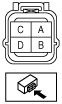
3. Disconnect the fuel pump unit connector.
4. Inspect for continuity between fuel pump unit connector terminals B and D.
-
• If there is no continuity, replace the fuel pump body.
• If as specified, carry out the “Circuit Open/Short Inspection”.
Circuit Open/Short Inspection
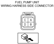
1. Inspect the following wiring harnesses as for open or short circuit (continuity check).
Open circuit
-
• If there is no continuity, there is an open circuit. Repair or replace the wiring harness.
-
― Fuel pump unit terminal B and fuel pump relay terminal A
― Fuel pump unit terminal D and body ground
Short circuit
-
• If there is continuity, there is a short circuit. Repair or replace the wiring harness.
-
― Fuel pump unit terminal B and power supply
― Fuel pump unit terminal B and body ground
― Fuel pump unit terminal D and power supply
Fuel Pump Hold Pressure Inspection
-
Warning
-
• Fuel line spills and leakage are dangerous. Fuel can ignite and cause serious injuries or death and damage. Always carry out the following procedure with the engine stopped.
-
Caution
-
• Disconnecting/connecting the quick release connector without cleaning it may cause damage to the fuel pipe and quick release connector. Always clean the quick release connector joint area before disconnecting/connecting using a cloth or soft brush, and make sure that it is free of foreign material.
-
Note
-
• Perform the following test only when directed.
1. Complete the “BEFORE SERVICE PRECAUTION”. (See BEFORE SERVICE PRECAUTION[L3 Turbo].)
2. Remove the battery and battery tray. (See BATTERY REMOVAL/INSTALLATION[L3 Turbo].)
-
Caution
-
• The quick release connector may be damaged if the tab is bent excessively. Do not expand the tab over the stopper.
3. Disconnect the quick release connector from the fuel tank. (See QUICK RELEASE CONNECTOR REMOVAL/INSTALLATION[L3 Turbo].)
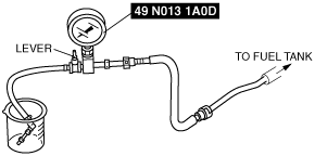
4. Turn the lever 90° against the hose of the SST to plug the SST outlet.
5. Push the SST quick release connector into the fuel pipe until a click is heard.
6. Set the fuel hose into a container to avoid fuel spills.
7. Start the fuel pump using the following procedure:
-
Using M-MDS
-
1. Connect the M-MDS to the DLC-2.
2. Start the fuel pump using the “FP“ simulation function.
-
Without using M-MDS
-
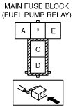
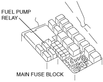
1. Remove the fuel pump relay.
-
Caution
-
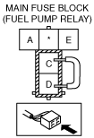
• Be careful to short the specified terminal as shorting the wrong terminal of the main fuse block may cause a malfunction.
2. Using a jumper wire, short fuel pump relay terminals C and D and connect the negative battery cable to start the fuel pump.
-
Caution
-
• The fuel pump may malfunction if it is operated without any fuel in the fuel tank (fuel pump idling). Constantly monitor the amount of fuel being discharged and immediately stop operation of the pump when essentially no fuel is being discharged.
8. Turn the ignition switch to the LOCK position.
9. Measure the fuel pump hold pressure after 5 min.
-
• If not as specified, replace the fuel pump after inspecting the following:
-
― Fuel line for clogging or leakage
-
Fuel pump hold pressure
-
More than 230 kPa {2.3 kgf/cm2, 33 psi}
10. Disconnect the jumper wire.
11. Disconnect the SST.
12. Connect the quick release connector. (See QUICK RELEASE CONNECTOR REMOVAL/INSTALLATION[L3 Turbo].)
13. Inspect all parts by performing “AFTER SERVICE PRECAUTION”. (See AFTER SERVICE PRECAUTION[L3 Turbo].)