 |
am3zzw00000154
FUEL INJECTOR INSPECTION[LF, L3]
id0114c2800700
Resistance Inspection
1. Turn the ignition switch to the LOCK position.
2. Remove the battery cover. (See BATTERY REMOVAL/INSTALLATION[LF, L3].)
3. Disconnect the negative battery cable.
4. Disconnect the fuel injector connector.
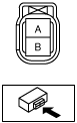
5. Inspect the resistance between fuel injector terminals A and B using a tester.
am3zzw00000154
|
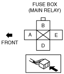
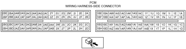
Circuit Open/Short Inspection
1. Disconnect the PCM connector. (See PCM REMOVAL/INSTALLATION[LF, L3].)
2. Inspect the following wiring harnesses for an open or short circuit (continuity check).
am3zzw00000155
|
am3zzw00002511
|
am3zzw00001777
|
Leakage Inspection
1. Follow “BEFORE SERVICE PRECAUTION” before performing any work operations to prevent fuel from spilling from the fuel system. (See BEFORE SERVICE PRECAUTION[LF, L3].)
2. Remove the battery cover. (See BATTERY REMOVAL/INSTALLATION[LF, L3]].)
3. Disconnect the negative battery cable.
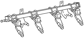
4. Remove the fuel injector and fuel distributor as a single unit. (See FUEL INJECTOR REMOVAL/INSTALLATION[LF, L3].)
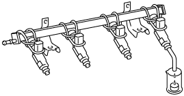
5. Fix the fuel injector to the fuel distributor with a wire or the equivalent.
am3zzw00000156
|
6. Connect the fuel hose.
7. Connect the negative battery cable.
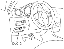
8. Connect the M-MDS to the DLC-2.
am3zzw00000157
|
9. Turn the ignition switch to the ON position.
10. Using the simulation function “FP”, start the fuel pump.
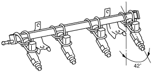
11. Tilt the fuel injector at an angle of 42° to inspect for leakage.
am3zzw00000158
|
12. Turn the ignition switch to the LOCK position and stop the fuel pump.
13. Remove the wire or the equivalent securing the fuel injector.
14. Install the fuel injector. (See FUEL INJECTOR REMOVAL/INSTALLATION[LF, L3].)
15. Inspect all related parts by performing “AFTER SERVICE PRECAUTION”. (See AFTER SERVICE PRECAUTION[LF, L3].)
Injection Volume Inspection
1. Follow “BEFORE SERVICE PRECAUTION” before performing any work operations to prevent fuel from spilling from the fuel system. (See BEFORE SERVICE PRECAUTION[LF, L3].)
2. Remove the battery cover. (See BATTERY REMOVAL/INSTALLATION[LF, L3].)
3. Disconnect the negative battery cable.
4. Remove the PCM.
5. Connect the PCM connector.
6. Remove the fuel injector and fuel distributor as a single unit. (See FUEL INJECTOR REMOVAL/INSTALLATION[LF, L3].)
7. Fix the fuel injector to the fuel distributor with a wire or the equivalent.
am3zzw00000159
|
8. Connect the corresponding fuel injector connector.
9. Connect the negative battery cable.
10. Connect the M-MDS to the DLC-2.
am3zzw00000157
|
11. Turn the ignition switch to the ON position.
12. Using the simulation function “FP”, start the fuel pump.
13. Ground the following PCM terminals using a jumper wire and measure the injection volume of each fuel injector.
am3zzw00001777
|
|
Fuel injector No. |
PCM terminal |
|---|---|
|
1
|
2BB
|
|
2
|
2BC
|
|
3
|
2BD
|
|
4
|
2AZ
|
14. Turn the ignition switch is to the LOCK position and stop the fuel pump.
15. Remove the wire or the equivalent securing the fuel injector.
16. Install the fuel injector. (See FUEL INJECTOR REMOVAL/INSTALLATION[LF, L3].)
17. Inspect all related parts by performing “AFTER SERVICE PRECAUTION”. (See AFTER SERVICE PRECAUTION[LF, L3].)
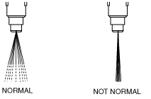
Atomization Inspection
1. Inspect the atomization status.
am3zzw00000161
|