 |
am5ezw00001554
CRANKSHAFT POSITION (CKP) SENSOR INSPECTION [LF, L3]
id0140a9800500
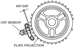
Air Gap Inspection
1. Verify that the CKP sensor is securely installed.
2. Using a thickness gauge, measure the air gap between the plate projections at the back of crankshaft pulley and the CKP sensor.
am5ezw00001554
|
Visual inspection
1. Remove the battery cover.
2. Disconnect the negative battery cable.
3. Remove the plug hole plate. (See PLUG HOLE PLATE REMOVAL/INSTALLATION [LF, L3].)
4. Perform the following procedure for easier access.
5. Disconnect the CKP sensor connector.
6. Remove the CKP sensor. (See CRANKSHAFT POSITION (CKP) SENSOR REMOVAL/INSTALLATION [LF, L3].)
7. Verify that there are no metal shavings on the CKP sensor.
Voltage Inspection
1. Idle the engine.
2. Measure the output voltage using a oscilloscope.
am3zzw00001753
|
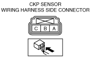
CKP sensor voltage
|
Terminal |
Voltage (V) |
Condition |
|---|---|---|
|
A
|
1.0 or less
|
Under any condition
|
|
B
|
4.8 or more
|
High output*
|
|
0.8 or less
|
Low output*
|
|
|
C
|
B+
|
Under any condition
|
Circuit Open/Short Inspection
am3zzw00001753
|
acxuuw00000119
|
1. Disconnect the PCM connector. (See PCM REMOVAL/INSTALLATION [LF, L3].)
2. Inspect the following wiring harnesses for open or short. (Continuity check)
Open circuit
Short circuit