KNOCK SENSOR (KS) INSPECTION[L3 Turbo]
id0140b6802800
-
Note
-
• Before performing the following inspection, make sure to follow the procedure as indicated in the troubleshooting flowchart. (See
HOW TO USE THIS MANUAL.)
Resistance Inspection
1. Turn the ignition switch to the LOCK position.
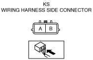
2. Disconnect the KS connector.
3. Measure the resistance between KS terminals A and B using a tester.
-
• If the KS is normal, but the PID value is out of specification, perform the “Circuit Open/Short Inspection”.
-
Specification
-
Approx. 4.87 megohms
Circuit Open/Short Inspection
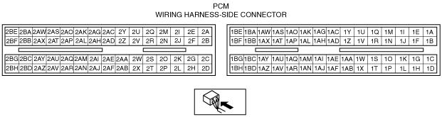
1. Disconnect the PCM connector. (See PCM REMOVAL/INSTALLATION[L3 Turbo].)
2. Inspect the following wiring harnesses for an open or short circuit. (Continuity check)
Open circuit
-
• If there is no continuity, there is an open circuit. Repair or replace the wiring harness.
-
― KS terminal A and PCM terminal 2U
― KS terminal B and PCM terminal 2V
Short circuit
-
• If there is continuity, there is a short circuit. Repair or replace the wiring harness.
-
― KS terminal A and power supply
― KS terminal A and body ground
― KS terminal B and power supply
― KS terminal B and body ground