|
1
|
VERIFY FREEZE FRAME DATA HAS BEEN RECORDED
• Has the FREEZE FRAME DATA been recorded?
|
Yes
|
Go to the next step.
|
|
No
|
Record the FREEZE FRAME DATA on the repair order, then go to the next step.
|
|
2
|
VERIFY RELATED SERVICE INFORMATION AVAILABILITY
• Verify related Service Information availability.
• Is any related Service Information available?
|
Yes
|
Perform repair or diagnosis according to the available Service Information.
• If the vehicle is not repaired, go to the next step.
|
|
No
|
Go to the next step.
|
|
3
|
VERIFY CURRENT INPUT SIGNAL STATUS
• Turn the ignition switch to the ON position (engine off).
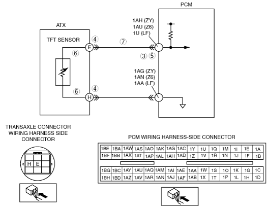
• Inspect the voltage at PCM terminal 1AH (ZY)/1AU (Z6)/1U (LF).
• Is the voltage 0.06 V or more?
|
Yes
|
Go to the intermittent concern troubleshooting procedure.
|
|
No
|
Go to the next step.
|
|
4
|
INSPECT TERMINAL CONDITION
• Turn the ignition switch to the LOCK position.
• Disconnect the ATX connector.
• Inspect for poor connection (such as damaged/pulled-out pins, corrosion).
• Are the terminals bent?
|
Yes
|
Repair or replace the terminals, then go to Step 8.
• If the terminals cannot be repaired, replace the wiring harness, then go to Step 8.
|
|
No
|
Go to the next step.
|
|
5
|
INSPECT TFT SENSOR CIRCUIT
• Turn the ignition switch to the ON position (engine off).
• Verify that the voltage changes to 4.67 V or more at PCM terminal 1AH (ZY)/1AU (Z6)/1U (LF) when ATX connector is disconnected.
• Does the voltage change?
|
Yes
|
Go to the next step.
|
|
No
|
Go to Step 7.
|
|
6
|
INSPECT TFT SENSOR CIRCUIT FOR SHORT TO GROUND
• Inspect for continuity between ATX terminals (transaxle case side) and body ground.
-
― E and body ground
― H and body ground
• Is there continuity?
|
Yes
|
Repair or replace the wiring harness, then go to Step 8.
|
|
No
|
Replace the TFT sensor, then go to Step 8.
|
|
7
|
INSPECT ATX CONNECTOR CIRCUIT FOR SHORT TO GROUND
• Turn the ignition switch to the LOCK position.
• Inspect for continuity between ATX terminal E (wiring harness-side) and body ground.
• Is there continuity?
|
Yes
|
Repair or replace the wiring harness, then go to the next step.
|
|
No
|
Go to the next step.
|
|
8
|
VERIFY TROUBLESHOOTING OF DTC P0712 COMPLETED
• Make sure to reconnect all the disconnected connectors.
• Clear the DTC from the memory using the M-MDS.
• Drive the vehicle under the following condition for 150 s or more.
-
― Vehicle speed (VSS PID) 20 km/h {12 mph} or more.
• Is the same DTC present?
|
Yes
|
Replace the PCM, then go to the next step.
|
|
No
|
Go to the next step.
|
|
9
|
VERIFY AFTER REPAIR PROCEDURE
• Perform the “After Repair Procedure”.
• Are any DTCs present?
|
Yes
|
Go to the applicable DTC inspection.
|
|
No
|
DTC troubleshooting completed.
|