 |
am3zzw00003083
TCM INSPECTION [FS5A-EL]
id051721800300
1. Measure the voltage at each terminal.
Terminal Voltage Table (Reference)
am3zzw00003083
|
|
Terminal |
Signal |
Connected to |
Test condition |
Voltage (V) |
Action |
|
|---|---|---|---|---|---|---|
|
A
|
—
|
—
|
—
|
—
|
—
|
|
|
B
|
CAN_H
|
Instrument cluster, ABS HU/CM, ABS/TCS HU/CM, DSC HU/CM
|
Because this terminal is for CAN, adequate determination by terminal voltage is not possible.
|
—
|
||
|
C
|
—
|
—
|
—
|
—
|
—
|
|
|
D
|
—
|
—
|
—
|
—
|
—
|
|
|
E
|
CAN_L
|
Instrument cluster, ABS HU/CM, ABS/TCS HU/CM, DSC HU/CM
|
Because this terminal is for CAN, adequate determination by terminal voltage is not possible.
|
—
|
||
|
F
|
Manual down
|
Down switch
|
Ignition switch ON
|
Detects down-shift operation of selector lever in M range
|
Below 1.0
|
• Inspect down switch
• Inspect related harness
|
|
Other
|
B+
|
|||||
|
G
|
Manual up
|
Up switch
|
Ignition switch ON
|
Detects up-shift operation of selector lever in M range
|
Below 1.0
|
• Inspect up switch
• Inspect related harness
|
|
Other
|
B+
|
|||||
|
H
|
—
|
—
|
—
|
—
|
—
|
|
|
I
|
B+
|
Main relay
|
Ignition switch OFF
|
Below 1.0
|
• Inspect battery
• Inspect related harness
|
|
|
Ignition switch ON
|
B+
|
|||||
|
J
|
Back-up power supply
|
Battery (positive terminal)
|
Under any condition
|
B+
|
• Inspect battery
• Inspect related harness
|
|
|
K
|
M range
|
M range switch
|
Ignition switch ON
|
Manual mode
|
Below 1.0
|
• Inspect M range switch
• Inspect related harness
|
|
Other
|
B+
|
|||||
|
L
|
GND
|
GND
|
Under any condition
|
Below 1.0
|
• Inspect related harness
|
|
|
M
|
GND
|
GND
|
Under any condition
|
Below 1.0
|
• Inspect related harness
|
|
|
N
|
—
|
—
|
—
|
—
|
—
|
|
|
O
|
B+
|
Main relay
|
Ignition switch OFF
|
Below 1.0
|
• Inspect battery
• Inspect related harness
|
|
|
Ignition switch ON
|
B+
|
|||||
|
P
|
Main relay control
|
Main relay
|
Ignition switch OFF
|
B+
|
• Inspect main relay
• Inspect related harness
|
|
|
Ignition switch ON
|
Below 1.0
|
|||||
|
Q
|
—
|
—
|
—
|
—
|
—
|
|
|
R
|
—
|
—
|
—
|
—
|
—
|
|
|
S
|
Oil pressure
|
Oil pressure switch
|
Ignition switch ON
|
Detects forward clutch pressure
|
Below 1.0
|
• Inspect oil pressure switch
• Inspect related harness
|
|
T
|
Shift up/Shift down signal
(Steering shift switch)
|
Steering shift switch
|
Up switch and down switch operated
(Steering shift switch)
|
Approx. 1.8
|
• Inspect steering shift switch
• Inspect related harness
|
|
|
Up switch operated
(Steering shift switch)
|
Approx. 2.3
|
|||||
|
Down switch operated
(Steering shift switch)
|
Approx. 3.0
|
|||||
|
Others
|
Approx. 5.0
|
|||||
|
U
|
Selector lever position
|
TR switch
(terminal C)
|
Ignition switch ON
|
P position
|
Approx. 4.6
|
• Inspect TR switch
• Inspect related harness
|
|
R position
|
Approx. 3.9
|
|||||
|
N position
|
Approx. 3.2
|
|||||
|
D range
M range
|
Approx. 2.5
|
|||||
|
V
|
Sensor GND
|
MAF/IAT sensor, A/F sensor, HO2S, Variable resistor, ECT sensor, TP sensor, MAP sensor, TFT sensor, TR switch
|
Under any condition
|
Below 1.0
|
• Inspect related harness
|
|
|
W
|
Cruise control switch
|
Cruise control switch
|
Ignition switch to the ON position
|
ON/OFF switch pressed in
|
Approx. 0
|
• Cruise control switch
• Inspect related harness
|
|
CANCEL switch pressed in
|
Approx. 1.1
|
|||||
|
SET/COAST switch pressed in
|
Approx. 3.1
|
|||||
|
RES/ACCEL switch pressed in
|
Approx. 4.2
|
|||||
|
Except above
|
Approx. 5.0
|
|||||
|
X
|
Steering shift switch GND
|
Steering shift switch
|
Under any condition
|
Below 1.0
|
• Inspect related harness
|
|
|
Y
|
Input/turbine speed sensor (–)
|
Input/turbine speed sensor
|
• Inspect using the wave profile.
|
• Inspect input/turbine speed sensor
• Inspect related harness
|
||
|
Z
|
Vehicle speed
|
VSS
|
• Inspect using the wave profile.
|
• Inspect VSS
• Inspect related harness
|
||
|
AA
|
ATF temperature
|
TFT sensor
|
Ignition switch ON
|
TFT 20 °C
{68 °F}
|
Approx. 3.3
|
• Inspect TFT sensor
• Inspect related harness
|
|
TFT 40 °C
{104 °F}
|
Approx. 2.4
|
|||||
|
TFT 60 °C
{140 °F}
|
Approx. 1.5
|
|||||
|
AB
|
Input/turbine speed sensor (+)
|
Input/turbine speed sensor
|
• Inspect using the wave profile.
|
• Inspect input/turbine speed sensor
• Inspect related harness
|
||
|
AC
|
Secondary gear rotating speed
|
Intermediate sensor
|
• Inspect using the wave profile.
|
• Inspect intermediate sensor
• Inspect related harness
|
||
|
AD
|
Pressure control solenoid A (+)
|
Pressure control solenoid A
|
• Inspect using the wave profile.
|
• Inspect pressure control solenoid A
• Inspect related harness
|
||
|
AE
|
Pressure control solenoid A (–)
|
Pressure control solenoid A
|
• Inspect using the wave profile.
|
• Inspect pressure control solenoid A
• Inspect related harness
|
||
|
AF
|
—
|
—
|
—
|
—
|
—
|
|
|
AG
|
Shift solenoid A control
|
Shift solenoid A
|
• Inspect using the wave profile.
|
• Inspect shift solenoid A
• Inspect related harness
|
||
|
AH
|
Shift solenoid D control
|
Shift solenoid D
|
Selector lever is at P, N, D (2GR, 4GR, 5GR), M (1GR) position
|
B+
|
• Inspect shift solenoid D
• Inspect related harness
|
|
|
Other
|
Below 1.0
|
|||||
|
AI
|
Shift solenoid F control
|
Shift solenoid F
|
1GR, 2GR, 3GR, 4GR
|
B+
|
• Inspect shift solenoid F
• Inspect related harness
|
|
|
5GR
|
Below 1.0
|
|||||
|
AJ
|
Shift solenoid B control
|
Shift solenoid B
|
• Inspect using the wave profile.
|
• Inspect shift solenoid B
• Inspect related harness
|
||
|
AK
|
Shift solenoid E control
|
Shift solenoid E
|
Detects TCC operation
|
B+
|
• Inspect shift solenoid E
• Inspect related harness
|
|
|
Other
|
Below 1.0
|
|||||
|
AL
|
Shift solenoid C control
|
Shift solenoid C
|
• Inspect using the wave profile.
|
• Inspect shift solenoid C
• Inspect related harness
|
||
|
AM
|
Pressure control solenoid B
|
Pressure control solenoid B
|
• Inspect using the wave profile.
|
• Inspect pressure control solenoid B
• Inspect related harness
|
||
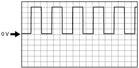
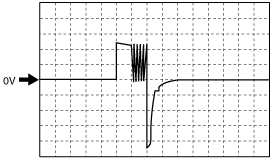
Inspection Using an Oscilloscope (Reference)
Secondary gear rotating speed signal
am3zzw00003084
|
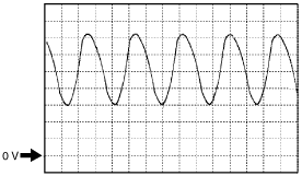
VSS signal
am3zzw00003084
|
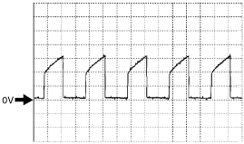
Input/turbine speed sensor signal
am3zzw00003085
|
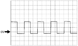
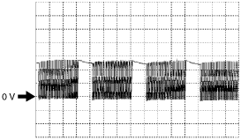
Pressure control solenoid A signal
(–)
am3zzw00003086
|
(+)
am3zzw00003087
|
Pressure control solenoid B signal
am3zzw00003088
|
Shift solenoid A control
am3zzw00003089
|
Shift solenoid B control
am3zzw00003090
|
Shift solenoid C control
am3zzw00003091
|