 |
am3zzw00001222
TRANSAXLE FLUID TEMPERATURE (TFT) SENSOR INSPECTION[FN4A-EL]
id0517a1801000
On-Vehicle Inspection
1. Remove the battery cover. (See BATTERY REMOVAL/INSTALLATION[ZJ, ZY, Z6].) (See BATTERY REMOVAL/INSTALLATION[LF, L3].)
2. Disconnect the negative battery cable.
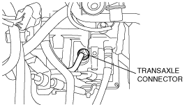
3. Remove the under cover.
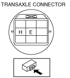
4. Disconnect the transaxle connector.
am3zzw00001222
|
5. Measure the resistance between the transaxle connector terminals E and H.
am3zzw00001223
|
Transaxle fluid temperature (TFT) sensor resistance
|
ATF temperature (°C {°F}) |
Resistance (kilohm) |
|---|---|
|
–20 {–4}
|
236—324
|
|
0 {32}
|
84.3—110
|
|
20 {68}
|
33.5—42.0
|
|
40 {104}
|
14.7—17.9
|
|
60 {140}
|
7.08—8.17
|
|
80 {176}
|
3.61—4.15
|
|
100 {212}
|
1.96—2.24
|
|
120 {248}
|
1.13—1.28
|
|
130 {266}
|
0.87—0.98
|
6. Install the under cover.
7. Connect the negative battery cable.
8. Install the battery cover. (See BATTERY REMOVAL/INSTALLATION[ZJ, ZY, Z6].) (See BATTERY REMOVAL/INSTALLATION[LF, L3].)
Off-Vehicle Inspection
1. Remove the control valve body. (See CONTROL VALVE BODY REMOVAL[FN4A-EL].)
2. Remove the coupler component.
am3zzw00001224
|
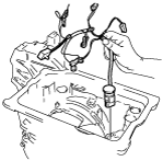
3. Place the TFT sensor and a thermometer in ATF as shown in the figure, and heat the ATF gradually.
4. Measure the resistance between the terminals of the TFT sensor.
am3zzw00001225
|
Transaxle fluid temperature (TFT) sensor
|
ATF temperature (°C {°F}) |
Resistance (kilohm) |
|---|---|
|
–20 {–4}
|
236—324
|
|
0 {32}
|
84.3—110
|
|
20 {68}
|
33.5—42.0
|
|
40 {104}
|
14.7—17.9
|
|
60 {140}
|
7.08—8.17
|
|
80 {176}
|
3.61—4.15
|
|
100 {212}
|
1.96—2.24
|
|
120 {248}
|
1.13—1.28
|
|
130 {266}
|
0.87—0.98
|
5. Install the coupler component.
6. Install the control valve body. (See CONTROL VALVE BODY INSTALLATION[FN4A-EL].)