 |
am3zzw00001227
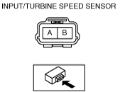
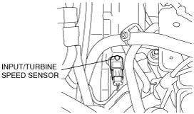
INPUT/TURBINE SPEED SENSOR INSPECTION[FN4A-EL]
id0517a1801200
1. Remove the battery cover. (See BATTERY REMOVAL/INSTALLATION[ZJ, ZY, Z6].) (See BATTERY REMOVAL/INSTALLATION[LF, L3].)
2. Disconnect the negative battery cable.
3. Remove the battery, battery box and battery tray. (See BATTERY REMOVAL/INSTALLATION[ZJ, ZY, Z6].) (See BATTERY REMOVAL/INSTALLATION[LF, L3].)
4. Disconnect the input/turbine speed sensor connector.
am3zzw00001227
|
5. Measure the resistance between the input/turbine speed sensor terminals.
am3zzw00001228
|
6. Connect the input/turbine speed sensor connector.
7. Install the battery, battery box and battery tray. (See BATTERY REMOVAL/INSTALLATION[ZJ, ZY, Z6].) (See BATTERY REMOVAL/INSTALLATION[LF, L3].)
8. Connect the negative battery cable.
9. Install the battery cover. (See BATTERY REMOVAL/INSTALLATION[ZJ, ZY, Z6].) (See BATTERY REMOVAL/INSTALLATION[LF, L3].)