 |
am3zzw00001215
TRANSAXLE RANGE (TR) SWITCH ADJUSTMENT[FN4A-EL]
id0517a1803700
1. Remove the battery cover. (See BATTERY REMOVAL/INSTALLATION[ZJ, ZY, Z6].) (See BATTERY REMOVAL/INSTALLATION[LF, L3].)
2. Disconnect the negative battery cable.
3. Remove the under cover.
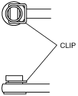
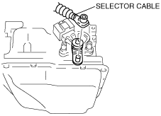
4. Remove the clip and disconnect the selector cable.
am3zzw00001215
|
5. Rotate the manual shaft to the converter housing side fully, then return two notches to set the N position.
am3zzw00002255
|
6. Disconnect the TR switch connector.
am3zzw00001217
|
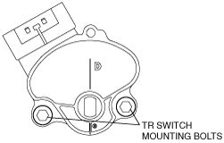
7. Loosen the TR switch mounting bolts.
am3zzw00001218
|
8. Measure the resistance between the TR switch terminals B and C.
am3zzw00001219
|
9. Adjust the switch to the point as follows.
10. Tighten the TR switch mounting bolts.
11. Move the selector lever to N position.
12. Verify that the TR switch is aligned with N position.
13. Connect the TR switch connector.
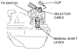
14. Install the clip to the selector cable as shown in the figure.
am3zzw00001220
|
15. Connect the selector cable to the manual shaft lever as shown in the figure.
am3zzw00001221
|
16. Inspect the TR switch operation. (See TRANSAXLE RANGE (TR) SWITCH INSPECTION[FN4A-EL].)
17. Install the under cover.
18. Connect the negative battery cable.
19. Install the battery cover. (See BATTERY REMOVAL/INSTALLATION[ZJ, ZY, Z6].) (See BATTERY REMOVAL/INSTALLATION[LF, L3].)