STEP
INSPECTION
ACTION
1
• Start the engine.
• Does the MIL turn off?
Yes
Troubleshooting completed.
No
Go to the next step.
2
• Inspect the DTC for the PCM ON-BOARD DIAGNOSTIC SYSTEM.
• Has DTC been recorded in memory?
Yes
Go to the applicable DTC troubleshooting procedure.
(See DTC TABLE[L3 Turbo].)
(See DTC TABLE[ZJ, ZY, Z6].)
(See DTC TABLE[MZ-CD 1.6 (Y6)].)
No
Go to the next step.
3
• Start the instrument cluster input/output check mode.
• Does the MIL turn off with a check code other than 26?
Yes
Go to the next step.
No
Replace the instrument cluster.
4
• Disconnect the negative battery cable.
• Measure the resistance between the DLC-2 terminals F and E.
• Is the resistance 54—66 ohms?
Yes
Go to the next step.
No
Go to Step 6.
5
• Inspect the DLC-2 terminals F and E for short to power supply or GND.
• Is there any malfunction?
Yes
Inspect the wiring harness and CAN system-related module.
Repair or replace the malfunctioning part.
No
Replace the instrument cluster.
6
• Turn the ignition switch off.
• Inspect the instrument cluster connector terminals for poor connection (such as damaged/pulled-out pins, and corrosion).
• Are the terminals normal?
Yes
Go to the next step.
No
Repair or replace the terminal.
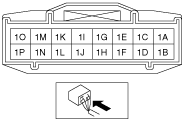
7
• Disconnect the negative battery cable.
• Measure the resistance between the instrument cluster connector terminals 1I and 1K.
• Is the resistance 114—126 ohms?
Yes
Inspect the wiring harness and CAN system-related module.
Repair or replace the malfunctioning part.
No
Replace the instrument cluster.