DIFFERENTIAL BACKLASH MEASUREMENT/ADJUSTMENT
id051700665400
Preparation Before Servicing
1. Print out the measurement/adjustment value input sheet. (See MEASUREMENT/ADJUSTMENT VALUE INPUT SHEET.)
-
Note
-
• When performing the measurement/adjustment, input the measured and calculated values into the measurement/adjustment value input sheet.
• If the measurement/adjustment value input sheet has already been printed out for the other measurements/adjustments, use the sheet.
Differential Backlash Measurement
-
Note
-
• Measure the tooth play (gap) between the side gear and pinion gear as the differential backlash.
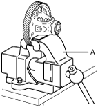
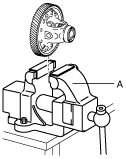
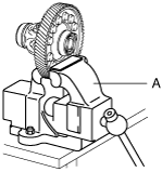
1. Secure the ring gear and differential in a vise.
-
Caution
-
• Insert a protective plate between the vise and the part so as not to damage the part.
A :Vise
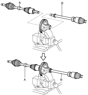
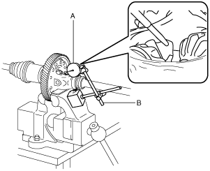
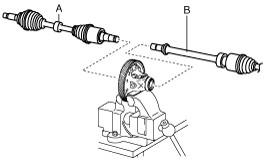
2. Assemble the front drive shaft (LH) and front drive shaft (RH) to the ring gear and differential.
-
Caution
-
• Because the front drive shaft (LH) clip is not required for the differential backlash measurement, do not assemble it.
A :Front drive shaft (LH)
B :Front drive shaft (RH)
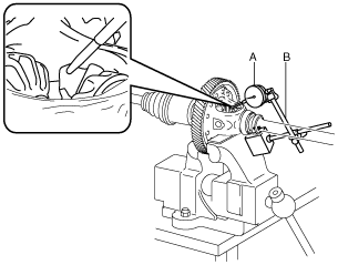
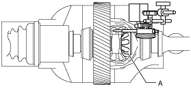
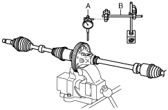
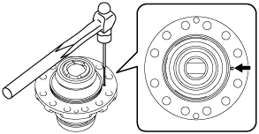
3. Set the dial gauge and magnetic stand as shown in the figure.
-
Caution
-
• To reduce error during the backlash measurement, set the dial gauge so that it is perpendicular to the teeth of the pinion gear.
A :Dial gauge
B :Magnetic stand
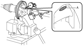
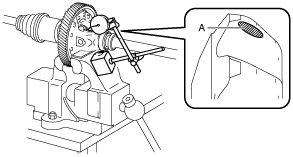
4. Set the dial gauge end to the pinion gear teeth.
-
Caution
-
• To reduce error during the backlash measurement, set the dial gauge end within the area shown in the figure.
A :Dial gauge end set area
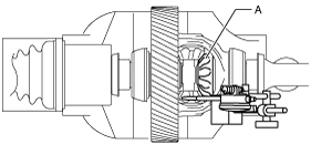
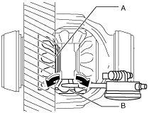
5. Secure the side gear on the front side by hand.
A :Secure by hand
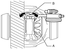
6. Move the pinion gear with the dial gauge by hand and measure the backlash.
-
Caution
-
• Because a difference occurs in the backlash measurement value if the secured side gear moves, move the pinion gear by hand so that the secured side gear does not move.
A :Secure by hand
B :Move the pinion gear by hand so that the secured side gear does not move.
7. Input the measured backlash of the side gear on the front side and the pinion gear into the measurement/adjustment value input sheet.
-
Note
-
• Input into section A in the measurement/adjustment value input sheet.
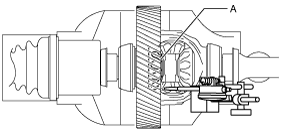
8. Secure the side gear on the rear side by hand.
A :Secure by hand
9. Move the pinion gear with the dial gauge by hand and measure the backlash.
-
Caution
-
• Because a difference occurs in the backlash measurement value if the secured side gear moves, move the pinion gear by hand so that the secured side gear does not move.
A :Secure by hand
B :Move the pinion gear by hand so that the secured side gear does not move.
10. Input the measured backlash of the side gear on the rear side and the pinion gear into the measurement/adjustment value input sheet.
-
Note
-
• Input into section B in the measurement/adjustment value input sheet.
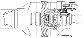
11. Set the dial gauge and magnetic stand to the pinion gear on the opposite side.
-
Caution
-
• To reduce error during the backlash measurement, set the dial gauge so that it is perpendicular to the teeth of the pinion gear.
A :Dial gauge
B :Magnetic stand
12. Set the dial gauge end to the pinion gear teeth.
-
Caution
-
• To reduce error during the backlash measurement, set the dial gauge end within the area shown in the figure.
A :Dial gauge end set area
13. Secure the side gear on the front side by hand.
A :Secure by hand
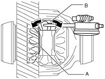
14. Move the pinion gear with the dial gauge by hand and measure the backlash.
-
Caution
-
• Because a difference occurs in the backlash measurement value if the secured side gear moves, move the pinion gear by hand so that the secured side gear does not move.
A :Secure by hand
B :Move the pinion gear by hand so that the secured side gear does not move.
15. Input the measured backlash of the side gear on the front side and the pinion gear into the measurement/adjustment value input sheet.
-
Note
-
• Input into section A in the measurement/adjustment value input sheet.
16. Secure the side gear on the rear side by hand.
A :Secure by hand
17. Move the pinion gear with the dial gauge by hand and measure the backlash.
-
Caution
-
• Because a difference occurs in the backlash measurement value if the secured side gear moves, move the pinion gear by hand so that the secured side gear does not move.
A :Secure by hand
B :Move the pinion gear by hand so that the secured side gear does not move.
18. Input the measured backlash of the side gear on the rear side and the pinion gear into the measurement/adjustment value input sheet.
-
Note
-
• Input into section B in the measurement/adjustment value input sheet.
19. Calculate the average value of the measured backlash of the side gear on the front side and the pinion gear.
20. Input the calculated average backlash value of the side gear on the front side and the pinion gear into the measurement/adjustment value input sheet.
-
Note
-
• The calculated average backlash value of the side gear on the front side and the pinion gear is the front side differential backlash.
21. Calculate the average value of the measured backlash of the side gear on the rear side and the pinion gear.
22. Input the calculated average backlash value of the side gear on the rear side and the pinion gear into the measurement/adjustment value input sheet.
-
Note
-
• The calculated average backlash value of the side gear on the rear side and the pinion gear is the rear side differential backlash.
23. Verify that the front side differential backlash and the rear side differential backlash satisfy the specification.
-
Specification
-
0.030—0.150 mm {0.0012—0.0059 in}
-
• After performing the differential backlash adjustment, if it exceeds the specification even with the thickest 0.95 mm {0.037 in} thrust washer assembled, disassemble the ring gear and differential and replace the differential gear case with a new one.
24. Remove the dial gauge and magnetic stand.
A :Dial gauge
B :Magnetic stand
25. Remove the front drive shaft (LH) and front drive shaft (RH).
A :Front drive shaft (LH)
B :Front drive shaft (RH)
26. Remove the ring gear and differential from the vise.
A :Vise
Differential Backlash Adjustment
1. Remove the dial gauge and magnetic stand.
A :Dial gauge
B :Magnetic stand
2. Remove the front drive shaft (LH) and front drive shaft (RH).
A :Front drive shaft (LH)
B :Front drive shaft (RH)
3. Remove the ring gear and differential from the vise.
A :Vise
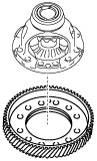
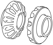
4. Remove the ring gear using the following procedure:
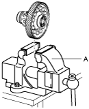
- (1) Secure the ring gear and differential in a vise.
-
-
Caution
-
• Insert a protective plate between the vise and the part so as not to damage the part.
A :Vise
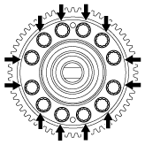
- (2) Loosen the bolts shown in the figure.
-
-
Caution
-
• If the bolts are removed, the differential may separate from the ring gear and fall off. Only loosen the bolts but do not remove them.
-
Note
-
• Change the securing position of the ring gear and differential with the vise and loosen all of the bolts shown in the figure.
- (3) Remove the ring gear and differential from the vise.
-
A :Vise
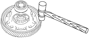
- (4) Remove the bolts shown in the figure.
-
- (5) Lightly tap the ring gear with a plastic hammer and remove the ring gear.
-
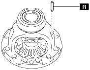
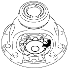
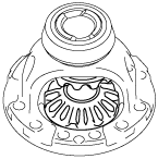
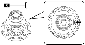
5. Remove the roll pin shown in the figure using a pin punch.
-
Note
-
• Use a pin punch with an end outer diameter of 3 mm {0.119 in} or more, and within 4 mm {0.157 in} and an end length of 60 mm {2.4 in} or more.
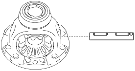
6. Remove the pinion shaft.
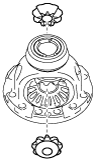
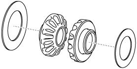
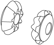
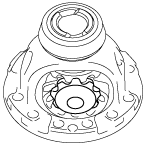
7. Remove the pinion gears using the following procedure:
- (1) Rotate the pinion gears as shown in the figure.
-
- (2) Remove the pinion gears.
-
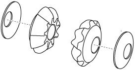
8. Remove the thrust washers from the pinion gears.
9. Remove the side gears.
10. Remove the thrust washers from the side gears.
11. Measure the thickness of the removed thrust washers from the side gears.
-
Note
-
• Recommended measuring instrument: Micrometer
12. Input the measured thrust washer thickness into the measurement/adjustment value input sheet.
13. Perform the following calculation to calculate the differential backlash gap.
-
Note
-
• The differential backlash gap is the difference between the differential backlash and the median value of the differential backlash specification.
-
Front side differential backlash gap = C - J
-
C: Front side differential backlash
J: Median value of differential backlash specification (0.090 mm {0.00354 in})
-
Note
-
Example
C: Front side differential backlash is 0.165 mm {0.00650 in}
Front side differential backlash gap = 0.165 mm {0.00650 in} - 0.090 mm {0.00354 in}= 0.075 mm {0.00295 in}
-
Rear side differential backlash gap = D - J
-
D: Rear side differential backlash
J: Median value of differential backlash specification (0.090 mm {0.00354 in})
-
Note
-
Example
D: Rear side differential backlash is 0.155 mm {0.00610 in}
Rear side differential backlash gap = 0.155 mm {0.00610 in} - 0.090 mm {0.00354 in}= 0.065 mm {0.00256 in}
14. Input the differential backlash gap into the measurement/adjustment value input sheet.
15. Perform the following calculation to calculate the thrust washer thickness gap.
-
Note
-
• The thrust washer thickness gap is the difference between the removed thrust washer thickness and the optimum thrust washer thickness.
• If the thrust washer thickness is thickened 0.1 mm {0.00394 in}, the differential backlash decreases approx. 0.08 mm {0.00315 in}.
-
Front side thrust washer thickness gap = K × 0.1 mm {0.00394 in}/ 0.08 mm {0.00315 in}
-
K: Front side differential backlash gap
-
Note
-
Example
K: Front side differential backlash gap is 0.075 mm {0.00295 in}
Front side thrust washer thickness gap = 0.075 mm {0.00295 in}× 0.1 mm {0.00394 in}/ 0.08 mm {0.00315 in}= 0.094 mm {0.00369 in}
-
Rear side thrust washer thickness gap = L × 0.1 mm {0.00394 in}/ 0.08 mm {0.00315 in}
-
L: Rear side differential backlash gap
-
Note
-
Example
L: Rear side differential backlash gap is 0.065 mm {0.00256 in}
Rear side thrust washer thickness gap = 0.065 mm {0.00256 in}× 0.1 mm {0.00394 in}/ 0.08 mm {0.00315 in}= 0.081 mm {0.00320 in}
16. Input the calculated thrust washer thickness gap into the measurement/adjustment value input sheet.
17. Perform the following calculation to calculate the optimum thrust washer thickness.
-
Optimum thrust washer thickness on front side = H + M
-
H: Thickness of removed front side thrust washer
M: Front side thrust washer thickness gap
-
Note
-
Example
H: Thickness of removed front side thrust washer is 0.810 mm {0.03189 in}
M: Front side thrust washer thickness gap is 0.094 mm {0.00369 in}
Thickness of optimum thrust washer on front side = 0.810 mm {0.03189 in}+ 0.094 mm {0.00369 in}= 0.904 mm {0.03559 in}
-
Thickness of optimum thrust washer on rear side = I + N
-
I: Thickness of removed rear side thrust washer
N: Rear side thrust washer thickness gap
-
Note
-
Example
I: Thickness of removed rear side thrust washer is 0.795 mm {0.0313 in}
N: Rear side thrust washer thickness gap is 0.081 mm {0.00320 in}
Thickness of optimum thrust washer on rear side = 0.795 mm {0.0313 in}+ 0.081 mm {0.00320 in}= 0.876 mm {0.03449 in}
18. Input the calculated optimum thrust washer thickness into the measurement/adjustment value sheet.
19. From the following table, select a thrust washer of a thickness closest to the calculated optimum thrust washer thickness.
-
Caution
-
• Select the same thickness of the thrust washers on the front and rear sides.
Measure the differential backlash again with the thrust washers of the same thickness assembled on the front and rear sides, and if the measurement value does not satisfy the specification, thrust washers of different thickness can be used on the front and rear sides.
|
Selected thrust washer thickness
|
|
0.95 mm {0.037 in}
|
|
0.90 mm {0.035 in}
|
|
0.85 mm {0.033 in}
|
|
0.80 mm {0.031 in}
|
|
0.75 mm {0.030 in}
|
20. Assemble the selected thrust washers to the side gears.
21. Assemble the side gears which have the thrust washers assembled to them.
22. Assemble the thrust washers to the pinion gears.
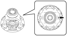
23. Assemble the pinion gears which have the thrust washers assembled to them using the following procedure:
- (1) Assemble the pinion gears which have the thrust washers assembled to them.
-
- (2) Rotate the pinion gears so that the pinion shaft holes of the differential gear case and the pinion gears are aligned as shown in the figure.
-
-
Note
-
• If the pinion shaft holes of the differential gear case and the pinion gears are not aligned, remove the pinion gears and reassemble them while changing the engagement with the side gears.
24. Assemble the pinion shaft.
-
Caution
-
• Assemble the pinion shaft so that the roll pin holes of the differential gear case and the pinion shaft are aligned.
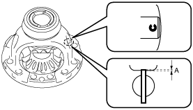
25. Assemble a new roll pin to the position shown in the figure using a pin punch.
-
Caution
-
• Assemble so that the end gap of the roll pin is positioned in the direction shown in the figure.
-
Note
-
• Use a pin punch with an end outer diameter of 5 mm {0.197 in} or more and within 8 mm {0.314 in}.
A :–0.5—0.5 mm {–0.01—0.01 in}
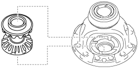
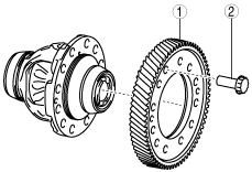
26. Assemble the ring gear using the following procedure:
|
1
|
Ring gear
|
|
2
|
12 Bolts (M13×1.0 bolt, length approx. 26.2 mm {1.03 in})
|
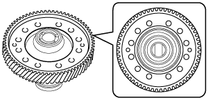
- (1) Assemble the ring gear.
-
-
Note
-
• Assemble the ring gear so that the differential holes and ring gear holes shown in the figure are aligned.
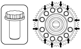
- (2) Assemble and temporarily tighten the bolts to the positions shown in the figure.
-
-
Note
-
• Bolt size: M13×1.0 bolt, length approx. 26.2 mm {1.03 in}
- (3) Secure the ring gear and differential in a vise.
-
-
Caution
-
• Insert a protective plate between the vise and the part so as not to damage the part.
A :Vise
- (4) Tighten the bolts shown in the figure.
-
-
Note
-
• Change the vise securing position of the ring gear and differential and tighten all of the bolts shown in the figure.
-
Tightening torque
-
152—176 N·m {16—17 kgf·m, 113—129 ft·lbf}
- (5) Remove the ring gear and differential from the vise.
-
A :Vise
27. Perform the differential backlash measurement. (See Differential Backlash Measurement.)