 |
am6zzw00012076
ENGINE DISASSEMBLY/ASSEMBLY [SKYACTIV-G 1.5, SKYACTIV-G 2.0, SKYACTIV-G 2.5]
id0110h6800500
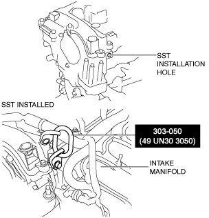
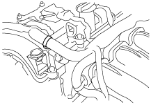
1. To enable to install the SST, disconnect the clip shown in the figure and set the wiring harness aside.
am6zzw00012076
|
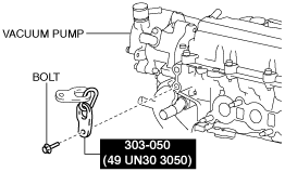
2. Install the SST and the following bolt to the position shown in the figure.
Engine front side
am6zzw00011712
|
Engine rear side
am6zzw00011713
|
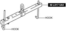
3. Engage the hooks of the SST (49 L017 5A0) to the SST (49 UN30 3050).
am6zzw00011714
|
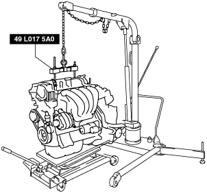
4. To ensure the safety of the work (control engine and transaxle sway), set a hoist as shown in the figure.
am6zzw00011715
|
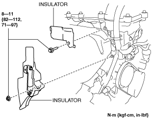
5. Remove the insulator shown in the figure.
am6zzw00011716
|
6. Remove the exhaust system. (See EXHAUST SYSTEM REMOVAL/INSTALLATION [SKYACTIV-G 1.5, SKYACTIV-G 2.0, SKYACTIV-G 2.5].)
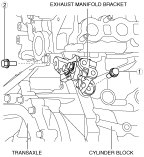
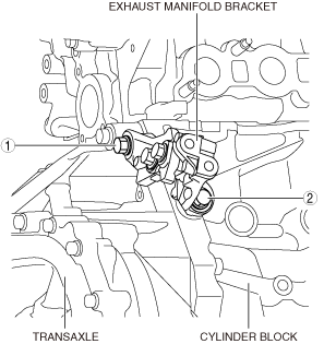
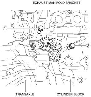
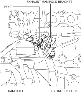
7. Remove the exhaust manifold bracket using the following procedure:
MTX
am3zzw00014970
|
ATX
am3zzw00014971
|
MTX
am3zzw00014972
|
ATX
am3zzw00014973
|
MTX
am3zzw00019157
|
ATX
ac3wzw00001942
|
MTX
am3zzw00019158
|
ATX
am3zzw00014971
|
MTX
am3zzw00014974
|
ATX
am3zzw00014975
|
8. Remove the bracket No.1 (drive shaft bracket). (See FRONT DRIVE SHAFT REMOVAL/INSTALLATION.)
9. Remove the starter. (See STARTER REMOVAL/INSTALLATION [SKYACTIV-G 1.5, SKYACTIV-G 2.0, SKYACTIV-G 2.5].)
10. Fix the drive plate using the crankshaft pulley lock bolt. (ATX)
11. Remove the torque converter installation nut from the starter installation hole. (See AUTOMATIC TRANSAXLE REMOVAL/INSTALLATION [FW6A-EL].)
12. Disconnect the engine and transaxle, and lower only the engine from the engine lifter.
13. Remove the generator. (See GENERATOR REMOVAL/INSTALLATION [SKYACTIV-G 1.5, SKYACTIV-G 2.0, SKYACTIV-G 2.5 (WITHOUT i-ELOOP)].) (See GENERATOR REMOVAL/INSTALLATION [SKYACTIV-G 1.5, SKYACTIV-G 2.0, SKYACTIV-G 2.5 (WITH i-ELOOP)].)
14. Remove the intake-air system. (See INTAKE-AIR SYSTEM REMOVAL/INSTALLATION [SKYACTIV-G 1.5, SKYACTIV-G 2.0, SKYACTIV-G 2.5].)
15. Remove the oil separator. (See POSITIVE CRANKCASE VENTILATION (PCV) VALVE REMOVAL/INSTALLATION [SKYACTIV-G 1.5, SKYACTIV-G 2.0, SKYACTIV-G 2.5].)
16. Remove the KS. (See KNOCK SENSOR (KS) REMOVAL/INSTALLATION [SKYACTIV-G 1.5, SKYACTIV-G 2.0, SKYACTIV-G 2.5].)
17. Remove the fuel injectors. (See FUEL INJECTOR REMOVAL/INSTALLATION [SKYACTIV-G 1.5, SKYACTIV-G 2.0, SKYACTIV-G 2.5].)
18. Remove the camshaft position (CMP) sensor. (See CAMSHAFT POSITION (CMP) SENSOR REMOVAL/INSTALLATION [SKYACTIV-G 1.5, SKYACTIV-G 2.0, SKYACTIV-G 2.5].)
19. Remove the vacuum pump. (See VACUUM PUMP REMOVAL/INSTALLATION [SKYACTIV-G 1.5, SKYACTIV-G 2.0, SKYACTIV-G 2.5].)
20. Remove the high pressure fuel pump and rear housing. (See HIGH PRESSURE FUEL PUMP REMOVAL/INSTALLATION [SKYACTIV-G 1.5, SKYACTIV-G 2.0, SKYACTIV-G 2.5].)
21. Remove the electric variable valve timing motor/driver. (See ELECTRIC VARIABLE VALVE TIMING MOTOR/DRIVER REMOVAL/INSTALLATION [SKYACTIV-G 1.5, SKYACTIV-G 2.0, SKYACTIV-G 2.5].)
22. Remove the oil filter. (See OIL FILTER REPLACEMENT [SKYACTIV-G 1.5, SKYACTIV-G 2.0, SKYACTIV-G 2.5].)
23. Remove the oil cooler. (if equipped) (See OIL COOLER REMOVAL/INSTALLATION [SKYACTIV-G 2.0].)
24. Remove the engine oil solenoid valve. (See ENGINE OIL SOLENOID VALVE REMOVAL/INSTALLATION [SKYACTIV-G 1.5, SKYACTIV-G 2.0, SKYACTIV-G 2.5].)
25. Remove the crankshaft position (CKP) sensor. (See CRANKSHAFT POSITION (CKP) SENSOR REMOVAL/INSTALLATION [SKYACTIV-G 1.5, SKYACTIV-G 2.0, SKYACTIV-G 2.5].)
26. Remove the dipstick.
27. Remove the ignition coil/ion sensors. (See IGNITION COIL/ION SENSOR REMOVAL/INSTALLATION [SKYACTIV-G 1.5, SKYACTIV-G 2.0, SKYACTIV-G 2.5].)
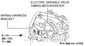
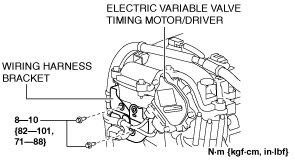
28. Remove the wiring harness bracket shown in the figure.
SKYACTIV-G 1.5
am3zzw00014684
|
SKYACTIV-G 2.0, SKYACTIV-G 2.5
am6zzw00011359
|
29. Remove the emission harness.
30. Remove the water pump drive belt. (See DRIVE BELT REMOVAL/INSTALLATION [SKYACTIV-G 1.5, SKYACTIV-G 2.0, SKYACTIV-G 2.5].)
31. Remove the water inlet pipe. (See CYLINDER HEAD GASKET REPLACEMENT [SKYACTIV-G 1.5, SKYACTIV-G 2.0, SKYACTIV-G 2.5].)
32. Remove the water pump. (See WATER PUMP REMOVAL/INSTALLATION [SKYACTIV-G 1.5, SKYACTIV-G 2.0, SKYACTIV-G 2.5].)
33. Remove the clutch cover and clutch disc. (MTX) (See CLUTCH UNIT REMOVAL/INSTALLATION [C66M-R].) (See CLUTCH UNIT REMOVAL/INSTALLATION [F66M-R].)
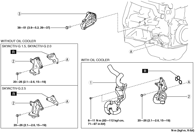
34. Remove in the order indicated in the table
35. Assemble in the reverse order of disassembly.
Exhaust side
am3zzw00016085
|
|
1
|
Oil cooler water pipe component (with oil cooler)
|
|
2
|
Oil filter body
|
|
3
|
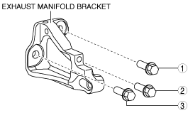
Exhaust manifold bracket
|
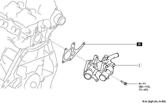
Engine rear side
am3zzw00020029
|
|
1
|
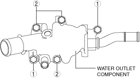
Water outlet component
|
Water Outlet Component Installation Note
1. Temporarily tighten the water outlet component installation bolts.
2. Tighten the bolts in the order shown in the figure.
am3zzw00020030
|
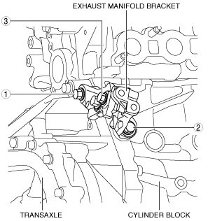
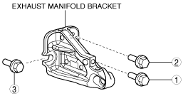
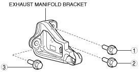
Exhaust Manifold Bracket Installation Note
SKYACTIV-G 1.5
1. Temporarily tighten the exhaust manifold bracket installation bolts.
2. Tighten the bolts in the order shown in the figure.
am3zzw00014685
|
SKYACTIV-G 2.0, SKYACTIV-G 2.5
am3uuw00012061
|
ac5uuw00002986
|
Oil Filter Body Installation Note
1. After tightening the three bolts, tighten the first tightened bolt to the specified tightening torque again.
Oil Cooler Water Pipe Component Installation Note
1. Install the oil cooler water pipe component in the order shown in the figure.
ac5wzw00004654
|