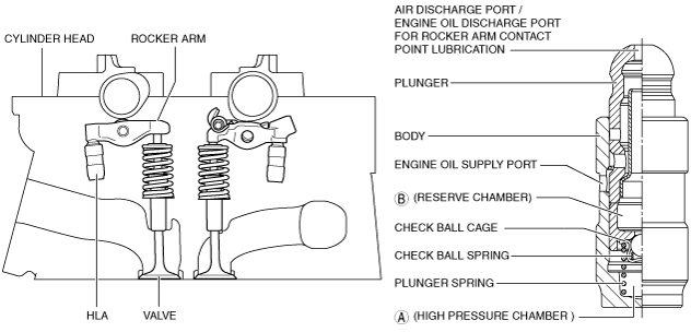
• The HLA is installed to the cylinder head.
am6zzn00003319
|
HYDRAULIC LASH ADJUSTER, ROCKER ARM [SKYACTIV-D 2.2]
id0110s5009200
Purpose, Function
HLA
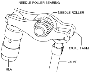
Rocker arm
Construction
HLA
am6zzn00003319
|
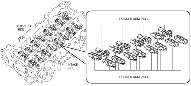
Rocker arm
ac5wzn00001726
|
ac5wzn00001727
|
ac5wzn00001728
|
|
Part name |
Function |
|---|---|
|
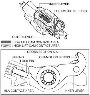
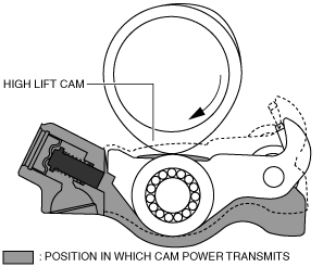
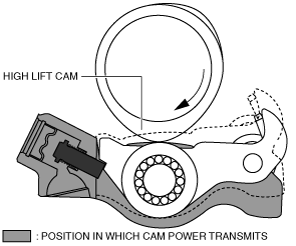
Outer lever
|
The outer lever is pressed to the down position by contact with the high lift cam of the exhaust camshaft.
|
|
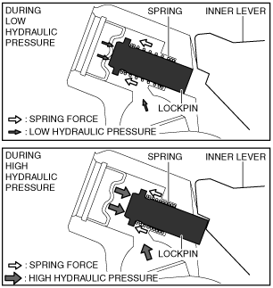
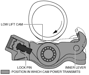
Inner lever
|
The inner lever is pressed to the down position by contact with the low lift cam of the exhaust camshaft. By fixing the inner lever with the lock pin, power is transmitted to the outer lever.
|
|
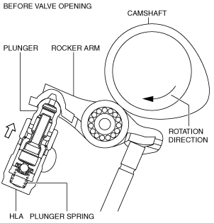
Lock pin
|
Fixes the inner lever to the outer lever.
|
|
Spring
|
Presses the lock pin back.
|
|
Lost-motion spring
|
Lifts up the inner lever by spring force when the inner lever is pressed down while not being fixed.
|
ac5wzn00001729
|
|
During low hydraulic pressure
|
The lock pin does not move because the spring force is greater than the hydraulic pressure.
|
|
During high hydraulic pressure
|
Because the hydraulic pressure is greater than the spring force, the lock pin is pressed out.
|
Operation
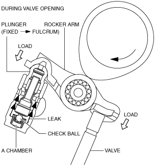
Before valve opening
1. The plunger presses up the rocker arm by the spring force of the plunger spring to maintain the valve clearance at 0 mm.
am3zzn00004293
|
During valve opening
1. If the cam presses down the rocker arm, load is applied to the plunger and valve.
2. If load is applied to the plunger, the hydraulic pressure in the high pressure chamber (A chamber) increases and the check ball closes the hydraulic passage.
3. If the hydraulic passage is closed, the plunger is fixed becoming the rocker arm pivot point because the volume of the engine oil in the high pressure chamber is not changed.
4. The rocker arm presses down the valve.
am3zzn00004294
|
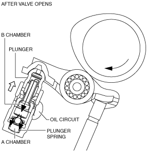
After valve opening
1. If load is not applied to the plunger, the plunger spring presses up the plunger (maintains valve clearance at 0 mm).
2. Because the capacity of the high pressure chamber (A chamber) increases in Step 1, the check ball is opened and engine oil flows from the reserve chamber (B chamber) to the high pressure chamber (A chamber) to prepare for the next step.
3. The oil in the reserve chamber (B chamber) which is decreased by supplying it to the high pressure chamber (A chamber), is supplied from the oil passage of the cylinder head.
am6zzn00003200
|
Rocker arm (No.2)
ac5wzn00001730
|
ac5wzn00001731
|
ac5wzn00001732
|
ac5wzn00001733
|