am6zzn00002666
|
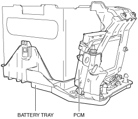
PCM [SKYACTIV-G 1.5, SKYACTIV-G 2.0, SKYACTIV-G 2.5]
id0140g5008400
Purpose/Function
|
Function |
Description |
|---|---|
|
Main relay control
|
• Supplies power to each part by switching the main relay on/off at the optimal timing according to the vehicle conditions.
|
|
Drive-by-wire control
|
• Calculates the optimum target throttle valve opening angle and controls the throttle valve actuator, which allows the driver to drive the vehicle at will.
• The drive-by-wire control is composed of the idle air control, accelerator control, traction control, excess engine speed control, overspeed control, electric variable valve timing cooperation control, engine oil temperature control, cruise control system, and the brake override system.
|
|
Hydraulic variable valve timing control
|
• Changes the exhaust valve timing according to engine operation conditions to improve engine output, fuel economy, and emission performance.
• Based on each input signal, the PCM determines the optimum exhaust valve timing according to the engine operation conditions. The PCM drives the OCV, and switches the oil passages of the hydraulic variable valve timing actuator to control the exhaust valve timing at optimum.
• Based on the coordination with the electric variable valve timing control and by increasing the amount of overlap during high engine loads, nitrogen oxide (NOx) occurring largely at high temperatures is reduced by re-circulating exhaust gas into the combustion chamber, which also reduces combustion temperature.
|
|
Electric variable valve timing control
|
• The PCM determines the optimum intake valve timing according to the engine operation conditions, and sends the motor drive signals to the electric variable valve timing driver. With the adoption of the electric drive system, variable intake valve timing can be controlled without any influence from the engine conditions, thus the fuel economy has been improved and pumping loss has been decreased.
• Based on the coordination with the hydraulic variable valve timing control and by increasing the amount of overlap during high engine loads, nitrogen oxide (NOx) occurring largely at high temperatures is reduced by re-circulating exhaust gas into the combustion chamber which reduces combustion temperature.
|
|
Fuel injection control
|
• Performs optimum fuel injection according to engine operation conditions.
• The PCM determines the engine operation conditions based on the signals from each input device and drives the fuel injectors at the optimal fuel injection time (fuel injection amount) and the fuel injection timing to inject fuel.
• Optimally controls combustion based on fuel injection amount, fuel injection timing, number of fuel injections, and the fuel pressure to achieve emission performance improvement and higher engine output.
|
|
Fuel pump control
|
• By switching the fuel pump discharge amount, reduced power consumption and improved fuel economy have been achieved.
• The PCM determines the optimum fuel pump discharge amount according to the engine operation conditions, and sends the fuel pump drive signal to the fuel pump control module.
|
|
High pressure fuel pump control
|
• Changes the fuel pressure applied to the fuel injector (according to engine operation conditions) to improve engine output and startability.
• The PCM determines the fuel pressure value corresponding to the engine operation conditions based on each input signal, and drives the spill valve control solenoid valve for optimum control of fuel pressure.
|
|
Electronic spark advance control
|
• Controls ignition for optimum timing (according to engine operation conditions).
• Serviceability has been improved by eliminating the necessity of ignition timing adjustment.
• The PCM determines the engine operation conditions (based on input signals from each sensor) and blocks current to the ignition coils at the calculated ignition timing. This causes the spark plugs to discharge (ignite) by the effect of electromagnetic mutual induction.
|
|
Purge control
|
• An appropriate amount of evaporative gas is fed into the intake manifold by the purge solenoid valve operation (according to the engine operation conditions). This ensures driveability and prevents release of evaporative gas into the atmosphere.
• The PCM drives the purge solenoid valve based on the signal from each control part.
|
|
A/F sensor heater control
|
• Based on the control of the A/F sensor heater, a stabilized oxygen concentration is detected (even at low exhaust temperatures), and feedback control of fuel injection (even at cold engine start) is made possible for improved cold temperature exhaust emission performance.
• Both emission performance and sensor protection have been improved by duty control of the heater (according to engine operation conditions (exhaust gas temperature)).
• A pre-heat has been adopted to prevent water, (produced from the exhaust system when the engine is started), from adhering to the sensor and damaging it.
|
|
HO2S heater control
|
• Based on the control of the HO2S heater, a stabilized oxygen concentration is detected (even at low exhaust temperatures), and feedback control of fuel injection (even at cold engine start) is made possible for improved cold temperature exhaust emission performance.
• Both emission performance and sensor protection have been improved by duty control of the heater (according to engine operation conditions (exhaust gas temperature)).
|
|
A/C cut-off control
|
• To improve drive performance and A/C compressor reliability, the A/C relay is turned off at the appropriate timing (according to the engine operation conditions), and the A/C operation is controlled.
|
|
Electrical fan control
|
• Through cooling of the radiator and condenser by operation of the cooling fan (according to vehicle conditions), engine reliability and cooling performance have been improved.
• The PCM determines the engine operation conditions (based on the signals from each sensor), and turns cooling fan relays No.1, No.2, and No.3 on/off to control the rotation speed of the cooling fan motor.
|
|
Starter cut-off control
|
• The PCM controls energization to the starter relay (according to an immobilizer system request) to improve security.
• While not in P or N position, the starter relay energization by the push button start is inhibited. (ATX)
• When the clutch pedal is not depressed, starter relay energization using the push button start is inhibited. (MTX)
|
|
Generator control
|
• Idling stability has been improved by optimum control of generator voltage (according to engine operation and electrical load conditions).
• The PCM determines the engine operation and electrical load conditions based on the input signals from each control part. It then uses this information to control the energization time of the generator field coils.
|
|
Immobilizer system
|
• The immobilizer system is a vehicle theft prevention device that only allows remote transmitters that have been previously programmed to the vehicle to start the engine.
|
|
i-stop control
|
• When the vehicle is stopped such as at a stop light, the i-stop control stops/starts the engine automatically to improve fuel economy and reduce exhaust gas and idling noise.
• The PCM determines whether to permit/inhibit i-stop control based on the signal from each input part and CAN communication.
• The i-stop control includes the engine stop control, engine restart control, electric AT oil pump driver control, and hill launch assist functions.
|
|
DC-DC converter control
|
• Stability of the power supply to the cabin has been achieved by preventing decreases in the power supply due to battery voltage decreases while the engine is restarted by the i-stop control.
• When the engine is restarted by the i-stop control, the PCM sends a battery voltage (DC-DC converter downstream voltage) boost request signal to the DC-DC converter.
|
|
Engine oil control
|
• The PCM reduces the oil pump load applied to the engine by controlling the appropriate engine hydraulic pressure (according to the engine operation conditions).
• The engine hydraulic pressure switches in two steps. When hydraulic pressure is not needed, the oil pump discharge amount is reduced by the operation of the engine oil solenoid valve.
|
|
Active air shutter control
|
• In the active air shutter control, the PCM controls the active air shutter actuator to open/close the shutter.
|
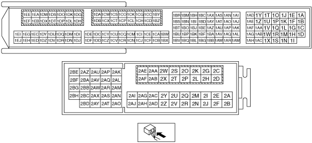
Construction
am6zzn00002666
|
ac5wzn00000035
|
Operation
|
Function |
Page |
|---|---|
|
Main relay control
|
|
|
Drive-by-wire control
|
|
|
Hydraulic variable valve timing control
|
|
|
Electric variable valve timing control
|
|
|
Fuel injection control
|
|
|
Fuel pump control
|
|
|
High pressure fuel pump control
|
|
|
Electronic spark advance control
|
|
|
Purge control
|
|
|
A/F sensor heater control
|
|
|
HO2S heater control
|
|
|
A/C cut-off control
|
|
|
Electrical fan control
|
|
|
Starter cut-off control
|
|
|
Generator control
|
|
|
Immobilizer system
|
(See IMMOBILIZER SYSTEM.)
|
|
i-stop control
|
|
|
DC-DC converter control
|
|
|
Engine oil control
|
|
|
Active air shutter control
|
(See ACTIVE AIR SHUTTER CONTROL.)
|
Fail-safe
|
DTC No. |
Fail-safe function |
|---|---|
|
P0601:00
|
• Restricts the upper limit of the engine speed.
• Stops the drive-by-wire control (throttle valve is open at approx. 8° by return spring force).
|
|
P0606:00
|
• Restricts the upper limit of the engine speed.
• Stops the drive-by-wire control (throttle valve is open at approx. 8° by return spring force).
|
|
P061B:00
|
• Restricts the upper limit of the engine speed.
|
|
P061D:00
|
• Restricts the upper limit of the engine speed.
|
|
P2107:00
|
• Restricts the upper limit of the engine speed.
• Stops the drive-by-wire control (throttle valve is open at approx. 8° by return spring force).
|
|
P2110:00
|
• Restricts the upper limit of the engine speed.
• Stops the drive-by-wire control (throttle valve is open at approx. 8° by return spring force).
|