 |
am3zzw00019571
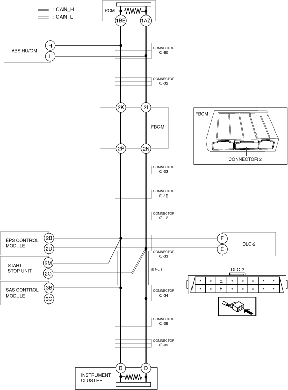
DETERMINING SHORT TO GROUND LOCATION (HS-CAN) [MZR 1.6 (R.H.D.)]
id100235000600
System Wiring Diagram
am3zzw00019571
|
Determination Procedure
|
Step |
Inspection |
Action |
|
|---|---|---|---|
|
1
|
INSPECT FOR SHORT TO GROUND BETWEEN FRONT BODY CONTROL MODULE (FBCM) AND INSTRUMENT CLUSTER
• Disconnect the negative battery cable.
• Disconnect connector 2 which has front body control module (FBCM) terminals 2P and 2N.
• Inspect for continuity at the following terminals:
• Is there continuity?
|
Yes
|
Go to Step 7.
|
|
No
|
Go to the next step.
|
||
|
2
|
INSPECT CAN LINE IN FRONT BODY CONTROL MODULE (FBCM) FOR SHORT TO GROUND
• Inspect for continuity at the following terminals:
• Is there continuity?
|
Yes
|
Replace the front body control module (FBCM) because there is a short to ground in the front body control module (FBCM).
|
|
No
|
Go to the next step.
|
||
|
3
|
INSPECT FOR SHORT TO GROUND BETWEEN CONNECTOR C-32 AND FRONT BODY CONTROL MODULE (FBCM)
• Disconnect connector C-32.
• Connect connector 2 which has front body control module (FBCM) terminals 2P and 2N.
• Inspect for continuity at the following terminals:
• Is there continuity?
|
Yes
|
Repair or replace the wiring harness between the connector C-32 and front body control module (FBCM) because the wiring harness is shorted to ground.
|
|
No
|
Go to the next step.
|
||
|
4
|
INSPECT FOR SHORT TO GROUND BETWEEN CONNECTOR C-60 AND CONNECTOR C-32
• Disconnect connector C-60.
• Connect connector C-32.
• Inspect for continuity at the following terminals:
• Is there continuity?
|
Yes
|
Repair or replace the wiring harness between the connector C-32 and connector C-60 because the wiring harness is shorted to ground.
|
|
No
|
Go to the next step.
|
||
|
5
|
INSPECT FOR SHORT TO GROUND BETWEEN ABS HU/CM AND CONNECTOR C-60
• Inspect for continuity at the following terminals:
• Is there continuity?
|
Yes
|
Go to the next step.
|
|
No
|
Go to Step 20.
|
||
|
6
|
INSPECT CAN LINE IN ABS HU/CM FOR SHORT TO GROUND
• Disconnect the ABS HU/CM connector.
• Inspect for continuity at the following terminals:
• Is there continuity?
|
Yes
|
Repair or replace the wiring harness between the ABS HU/CM and connector C-60 because the wiring harness is shorted to ground.
|
|
No
|
Replace the ABS HU/CM because there is a short to ground in the ABS HU/CM.
|
||
|
7
|
INSPECT FOR SHORT TO GROUND BETWEEN CONNECTOR C-03 AND INSTRUMENT CLUSTER
• Disconnect connector C-03.
• Inspect for continuity at the following terminals:
• Is there continuity?
|
Yes
|
Go to the next step.
|
|
No
|
Repair or replace the wiring harness between connector C-03 and front body control module (FBCM) because the wiring harness is shorted to ground.
|
||
|
8
|
INSPECT FOR SHORT TO GROUND BETWEEN CONNECTOR C-12 AND INSTRUMENT CLUSTER
• Disconnect connector C-12.
• Inspect for continuity at the following terminals:
• Is there continuity?
|
Yes
|
Go to the next step.
|
|
No
|
Repair or replace the wiring harness between connector C-03 and connector C-12 because the wiring harness is shorted to ground.
|
||
|
9
|
INSPECT FOR SHORT TO GROUND BETWEEN CONNECTOR C-12 AND CONNECTOR C-33
• Disconnect connector C-33.
• Connect connector C-12.
• Connect connector C-03.
• Connect connector 2 which has front body control module (FBCM) terminals 2P and 2N.
• Inspect for continuity at the following terminals:
• Is there continuity?
|
Yes
|
Repair or replace the wiring harness between connector C-12 and connector C-33 because the wiring harness is shorted to ground.
|
|
No
|
Go to the next step.
|
||
|
10
|
INSPECT FOR SHORT TO GROUND BETWEEN CONNECTOR C-33 AND DLC-2
• Inspect for continuity at the following terminals:
• Is there continuity?
|
Yes
|
Repair or replace the wiring harness between DLC-2 and connector C-33 because the wiring harness is shorted to ground.
|
|
No
|
Go to the next step.
|
||
|
11
|
INSPECT FOR SHORT TO GROUND BETWEEN EPS CONTROL MODULE AND CONNECTOR C-33
• Inspect for continuity at the following terminals:
• Is there continuity?
|
Yes
|
Go to the next step.
|
|
No
|
Go to Step 13.
|
||
|
12
|
INSPECT CAN LINE IN EPS CONTROL MODULE FOR SHORT TO GROUND
• Disconnect the EPS control module connector.
• Inspect for continuity at the following terminals:
• Is there continuity?
|
Yes
|
Repair or replace the wiring harness between the EPS control module and connector C-33 because the wiring harness is shorted to ground.
|
|
No
|
Replace the EPS control module because there is a short to ground in the EPS control module.
|
||
|
13
|
INSPECT FOR SHORT TO GROUND BETWEEN START STOP UNIT AND CONNECTOR C-33
• Inspect for continuity at the following terminals:
• Is there continuity?
|
Yes
|
Go to the next step.
|
|
No
|
Go to Step 15.
|
||
|
14
|
INSPECT CAN LINE IN START STOP UNIT FOR SHORT TO GROUND
• Disconnect the start stop unit connector.
• Inspect for continuity at the following terminals:
• Is there continuity?
|
Yes
|
Repair or replace the wiring harness between the start stop unit and connector C-33 because the wiring harness is shorted to ground.
|
|
No
|
Replace the start stop unit because there is a short to ground in the start stop unit.
|
||
|
15
|
INSPECT CAN LINE IN JB No.2 FOR SHORT TO GROUND
• Disconnect connector C-34.
• Connect connector C-33.
• Inspect for continuity at the following terminals:
• Is there continuity?
|
Yes
|
Replace the JB No.2 because there is a short to ground in the JB No.2.
|
|
No
|
Go to the next step.
|
||
|
16
|
INSPECT FOR SHORT TO GROUND BETWEEN SAS CONTROL MODULE AND CONNECTOR C-34
• Inspect for continuity at the following terminals:
• Is there continuity?
|
Yes
|
Go to the next step.
|
|
No
|
Go to Step 18.
|
||
|
17
|
INSPECT CAN LINE IN SAS CONTROL MODULE FOR SHORT TO GROUND
• Disconnect the SAS control module connector.
• Inspect for continuity at the following terminals:
• Is there continuity?
|
Yes
|
Repair or replace the wiring harness between the SAS control module and connector C-34 because the wiring harness is shorted to ground.
|
|
No
|
Replace the SAS control module because there is a short to ground in the SAS control module.
|
||
|
18
|
INSPECT FOR SHORT TO GROUND BETWEEN CONNECTOR C-09 AND CONNECTOR C-34
• Disconnect connector C-09.
• Connect connector C-34.
• Inspect for continuity at the following terminals:
• Is there continuity?
|
Yes
|
Repair or replace the wiring harness between the connector C-34 and connector C-09 because the wiring harness is shorted to ground.
|
|
No
|
Go to the next step.
|
||
|
19
|
INSPECT CAN LINE IN INSTRUMENT CLUSTER FOR SHORT TO GROUND
• Disconnect the instrument cluster connector.
• Inspect for continuity at the following terminals:
• Is there continuity?
|
Yes
|
Repair or replace the wiring harness between the instrument cluster and connector C-09 because the wiring harness is shorted to ground.
|
|
No
|
Replace the instrument cluster because there is a short to ground in the instrument cluster.
|
||
|
20
|
INSPECT CAN LINE IN PCM FOR SHORT TO GROUND
• Disconnect the PCM connector.
• Inspect for continuity at the following terminals:
• Is there continuity?
|
Yes
|
Repair or replace the wiring harness between the PCM and connector C-60 because the wiring harness is shorted to ground.
|
|
No
|
Replace the PCM because there is a short to ground in the PCM.
|
||